0195
Transmit Performance of a Metamaterial Slab as a Passive RF Shimming Element for 3T MRI1Electrical and Computer Engineering, University of Alberta, Edmonton, AB, Canada, 2Oncology, University of Alberta, Edmonton, AB, Canada, 3Medical Physics, Cross Cancer Institute, Edmonton, AB, Canada
Synopsis
At higher static magnetic field strengths (3T) characteristic regions of low transmit fields occur that degrade the quality and diagnostic efficacy of MRI. Here we present the design, simulation, and measurement of thin (2cm), lightweight metamaterial (MTM) slabs for 3T that manipulate the field produced by a birdcage (BC) volume resonator for improved transmit performance. In a torso-sized phantom, a measured 39% increase in the mean flip angle and 4.9% reduction in the percent coefficient of variation was found, while the specific absorption rate normalized to the mean transmit field was reduced by 32%.
Introduction
As the Larmor frequency increases with higher static magnetic field strengths, the high dielectric permittivity and shape of the human body distorts the radio frequency (RF) right circularly polarized transmit field ($$$B_1^+$$$) that produces MR excitation. This results in characteristic field nulls in the anterior and posterior region of the body when using the birdcage coil (BC) volume resonator, which is a particular problem for abdominal or thoracic imaging at 3T. The gain in signal-to-noise in body imaging from 1.5T to 3T is thus compromised by signal loss and inhomogeneous image contrast1.High permittivity pads have been employed to reduce the field nulls, improve transmit efficiency and reduce specific absorption rate (SAR)2. However, dielectric pads are bulky, heavy (4-20 kg), are restricted to the relative permittivity values of naturally occurring materials (1-500), have associated losses (0.2-10 S/m), interfere with the placement and operation of receive arrays and do not contribute to channel density (ie. cannot be employed receive elements). The use of dual-channel transmit MRI with the BC can result in similar levels of improvement3, but the greatest improvement is obtained when both methods are used concurrently2. Conversely, metamaterials (MTMs) can be lighter, can be tuned and optimized by varying their effective electromagnetic parameters, and can provide equivalent or better performance4,5. Here we introduce the use of a MTM slab based on 2D transmission line elements and compare the imaging performance when employed on both the anterior and posterior sides of a large torso-sized phantom6, Furthermore, the slab can be employed as a receive array, thereby providing improvements in both transmit and receive (see companion abstract submitted to this conference7).
Methods
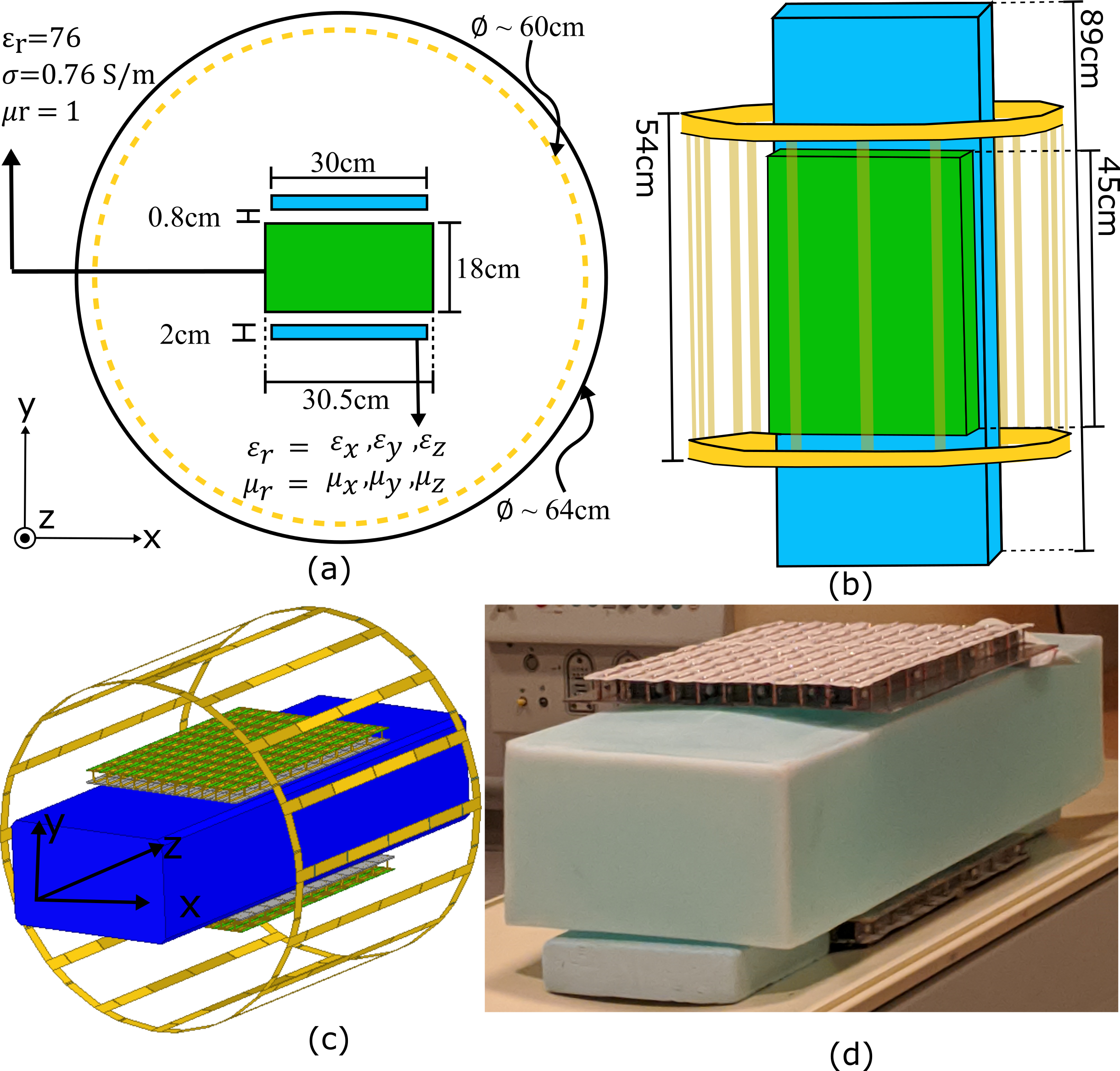
The MTM slab consists of 11×10 unit-cells, where adjacent 1D transmission line sections are connected by broadside mutual inductance coupling in the x-direction, resulting in propagation along 2 dimensions (see Figure 1(a)). The MTM acts as slab of material with anisotropic permittivity: $$$ε=ε_0 diag(ε_x,ε_y,ε_z )$$$ and permeability: $$$μ=μ_0 diag(μ_x,μ_y,μ_z)$$$. The MTM slab is designed and tuned so that the $$$ε_y$$$, $$$μ_z$$$ and $$$μ_x$$$ are the primary electromagnetic parameters giving rise to the altered transmit field, where a large effective $$$ε_y$$$ is expected, making the MTM slab mimic a high permittivity slab of material. The method of determining the correct tuning is described in reference (6) and the geometry of each unit cell is described in our abstract detailing its use as a receive array7. The capacitive tuning elements consist of overlapping copper strips (18μm thick) on thin ROGERS 3006TM substrate (0.25mm thick, ε=6.15, tanδ=0.002), while a bottom 2mm thick polycarbonate substrate provides mechanical support along with PVC structural blocks and nylon screws. In simulation (Ansys, HFSS) the copper is modelled with a conductivity of 5.8×10⁷S/m and the BC is designed to closely match the field profile of the BC used in the Philips Achieva 3T scanner. Using 1kW RMS quadrature drive, simulated fields were compared to flip angle (FA) maps acquired by varying the prescribed FA (50°, 100° and 150°) using a 2D multi-slice SPGR sequence and pixelwise least squares fitting according to the SPGR equation8 (500Hz/pixel, 70×70×33 matrix, 6×6×6mm3 resolution, TE=2.6ms, TR=800ms) in a phantom with 3.6 g/L NaCl and 1.96 g/L CuSO4⋅5H2O aqueous solution9.Results and Discussion
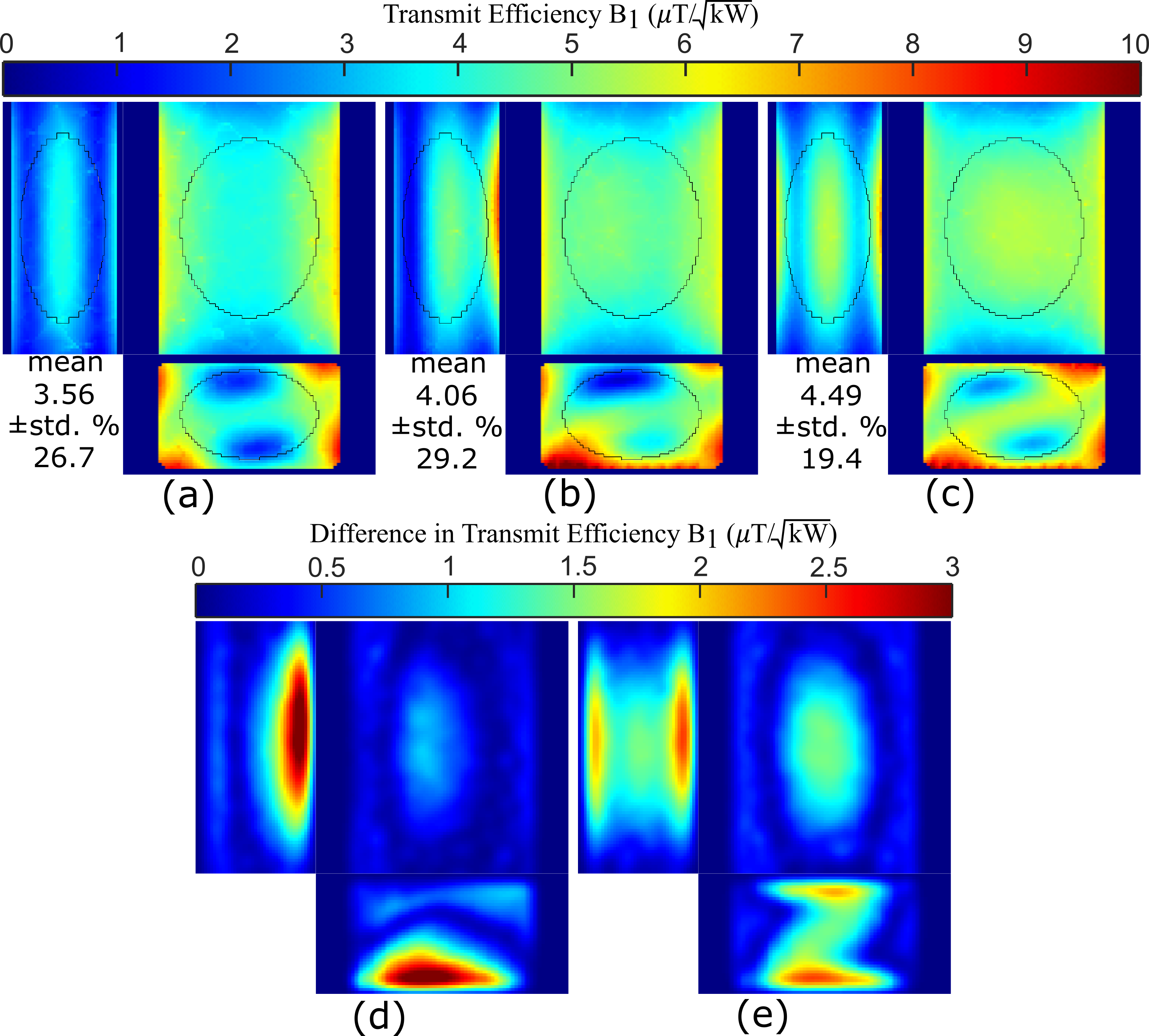
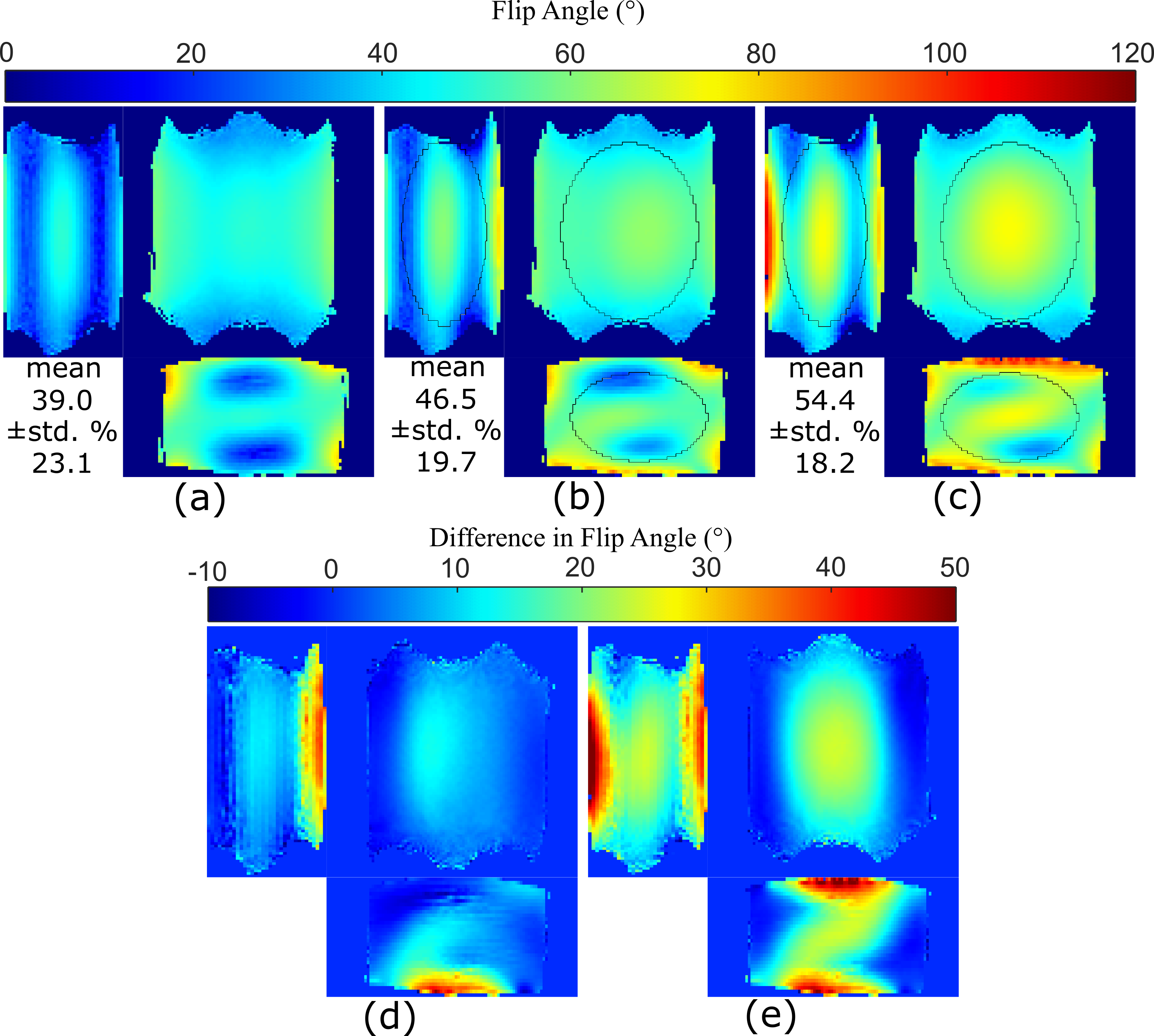
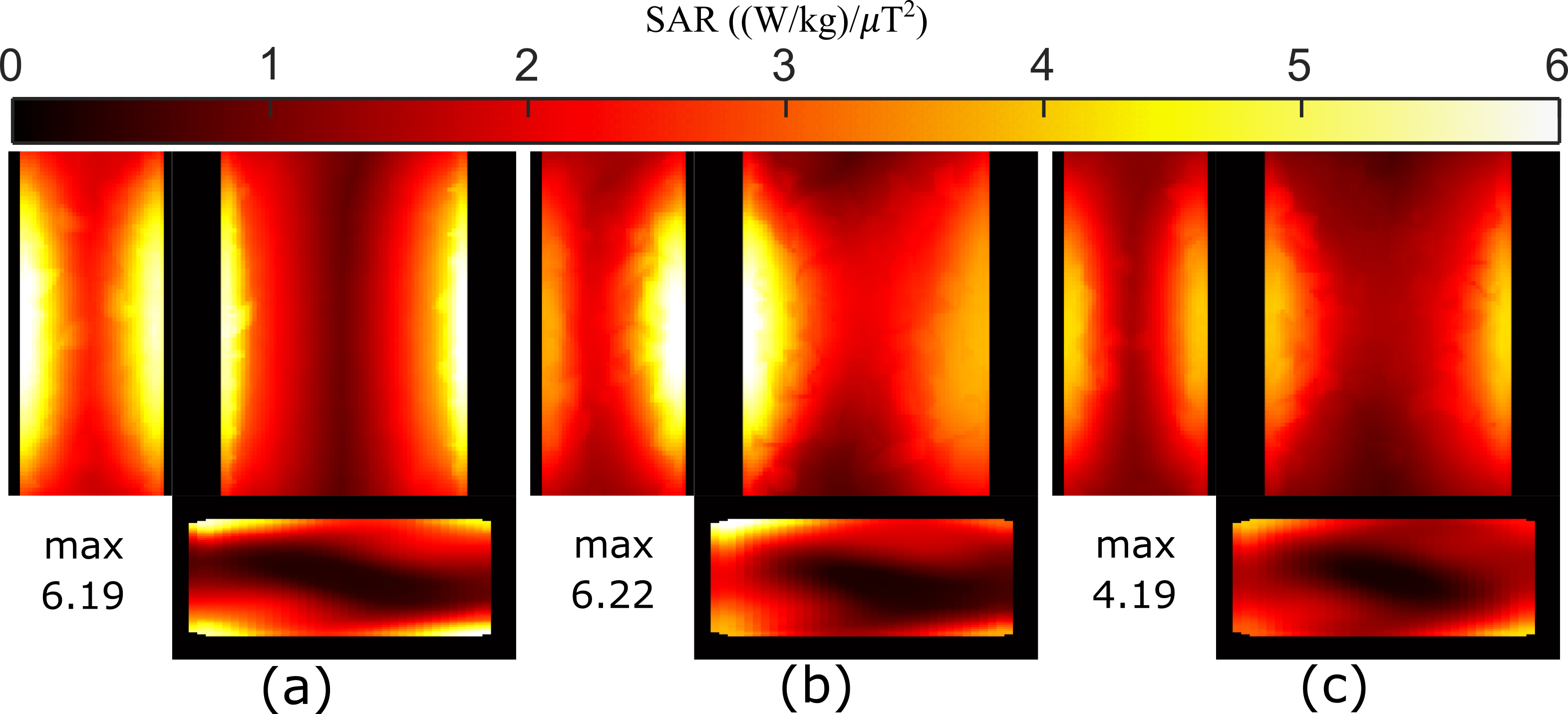
The simulated transmission efficiency maps in three orthogonal slices are shown in Figure 2 with (a) only the BC, (b) with a single MTM slab and (c) with two MTM slabs. In simulation, the MTM slabs had a negligible effect on the input impedance of the BC. The relative improvement throughout is observed in difference maps of Figure 2(d) with a single MTM slab and (e) with two MTM slabs compared to the BC alone. The simulated transmit efficiency results closely match the measured FA maps, shown in the same order in Figure 3. The largest difference is a 39% vs. 27% increase in transmit efficiency with two MTM slabs observed in measurement compared to simulation, which may be partially explained by positioning differences of the region of interest ellipsoid (11.5×15×7.5mm3 radii). The overall FA homogeneity is improved (CoV decreased from 23.1% to 18.2%), but the greatest benefit is obtained by the elimination of voids in the field near the anterior and posterior. Also, a significant improvement in SAR is observed in Figure 4, where maximum intensity projection maps demonstrate that the 10g averaged local SAR normalized to a mean 1µT transmit field is reduced from 6.19W/kg with only the BC (Figure 4(a)) to 4.19W/kg with two MTM slabs, .Conclusion
The MTM slab improves RF field homogeneity in a homogeneous phantom (CoV reduced by 4.9%), while reducing the local 10g averaged SAR by 32%. Improvement was most evident in the elimination of null regions in the RF transmit field. Future work will focus on in-vivo demonstration and effective medium description of the MTM slab.Acknowledgements
This work was supported by the Alberta Innovates postdoctoral fellowship in health innovation, a studentship from the Office of the Provost and VP of the University of Alberta, and research grants from the Natural Sciences and Engineering Research Council (NSERC) of Canada Discovery Grants program. We thank CMC Microsystems for software access and support by the University of Alberta Faculty of Engineering IT. The Cross Cancer Institute machine shop provided support manufacturing structural elements of the MTM. We thank Philips Healthcare for training (AMM) and technical support, and Dr. R. Luechinger for the PATI program used to transfer data.References
1.Merkle EM, Dale BM. Abdominal MRI at 3.0 T: The Basics Revisited American Journal of Roentgenology (2006) 186(6):1524-1532
2.Brink WM, van den Brink JS, Webb AG. The effect of high-permittivity pads on specific absorption rate in radiofrequency-shimmed dual-transmit cardiovascular magnetic resonance at 3T. J Cardiovasc Magn Reson. (2015) 17(1):82
3.Brink WM, Gulani V, Webb AG, Clinical applications of dual-channel transmit MRI: A review. J. Magn. Reson. Imaging, (2015) 42: 855-869
4.Gomez TSV, Dubois M, Jomin P, Benamara M, Berrahou D, Georget E, Antonakakis T, Bendahan D, Kober F, Enoch S, and Abdeddaim R. Lightweight Metasurface Pads for Passive RF Shimming in 3T Abdominal Imaging Proc. Intl. Soc. Mag. Reson. Med. (2021) 29:1405
5.Vorobyev,V, Shchelokova A, Efimtcev A, et al. Improving Homogeneity in Abdominal Imaging at 3T with Light, Flexible, and Compact Metasurface. Magn Reson Med. (2021)
6.Maunder A, De Zanche N, Iyer AK. "Design and Modelling of Metamaterial Resonators for 3 Tesla Magnetic Resonance Imaging," 2021 International Applied Computational Electromagnetics Society Symposium (ACES) (2021)
7.Maunder A, Iyer AK and De Zanche N. Hybrid 3T 8-channel Array Using a Metamaterial Slab and Companion Loop Elements: Comparison to a Conventional Array Paper submitted at: Proc. Intl. Soc. Mag. Reson. Med (2022) London, UK
8.Deoni SCL. High-resolution T1 mapping of the brain at 3T with driven equilibrium single pulse observation of T1 with high-speed incorporation of RF field inhomogeneities (DESPOT1-HIFI). J Magn Reson Imaging. (2007) 26:1106–1111
9.Och JG, Clarke GD, Sobol WT, Rosen CW, Mun SK. Acceptance testing of magnetic resonance imaging systems: report of AAPM nuclear magnetic resonance task group No. 6. Med Phys. (1992) 19:217–229
Figures