0194
Development of a Broadside-Coupled Split-Ring Resonator-Based Metasurface to Improve MRI at Ultra-High Fields1BioMedical Engineering and Imaging Institute (BMEII), Icahn School of Medicine at Mount Sinai, Manhattan, NY, United States, 2Diagnostic, Molecular and Interventional Radiology, Icahn School of Medicine at Mount Sinai, Manhattan, NY, United States
Synopsis
There is a growing interest in ultra-high field magnetic resonance neuroimaging because of the greater signal-to-noise ratio (SNR) compared with conventional field strengths. However, visualization at these higher field strengths and Larmor frequencies is challenged by wavelength effects, compromising anatomical coverage of commercial coils. A novel metasurface based on a hybrid structure consisting of an array of broadside-coupled split-ring resonators and high permittivity materials was designed to augment signal at the 7 Tesla 1H Larmor frequency. This reusable surface device markedly improves SNR in caudal head structures that have historically been limited by poor signal.
Introduction
Ultra-high field (UHF) MRI systems (7T+) leverage increased SNR over conventional field strengths for anatomical and functional MRI of human brain. However, challenges associated with wavelength effects at UHF, such as transmit radiofrequency (RF) magnetic field $$$(B_1^+)$$$ inhomogeneity, limit broad application of UHF MRI. One area of weakness is the posterior fossa, where reduction in coil transmit efficiency significantly reduces SNR compared with other brain regions.Approaches to resolving this issue of inhomogeneity include parallel transmit systems (PTx)1, and passive RF shimming devices such as high permittivity materials (HPM)2, metasurfaces3, or passive RF arrays4. However, these methods have some drawbacks including unstable material parameters of dielectric pads, high-cost and complexity of PTx systems.
Metamaterials, artificial structures that can be designed to control the propagation of electromagnetic (EM) waves, so they are very promising for engineering EM devices5. Several studies have reported how metamaterials may enhance MRI signal6,7. We developed a simple device named the broadside-coupled split-ring-resonator (BC-SRR)-based metasurface. Placed against the posterior caudal head inside a head coil, this device improves transmit efficiency and signal sensitivity in this region where both are typically challenging using conventional architecture.
The aim of this study was to assess the effect of this new metasurafce design on improving brain signal at 7T.
Method
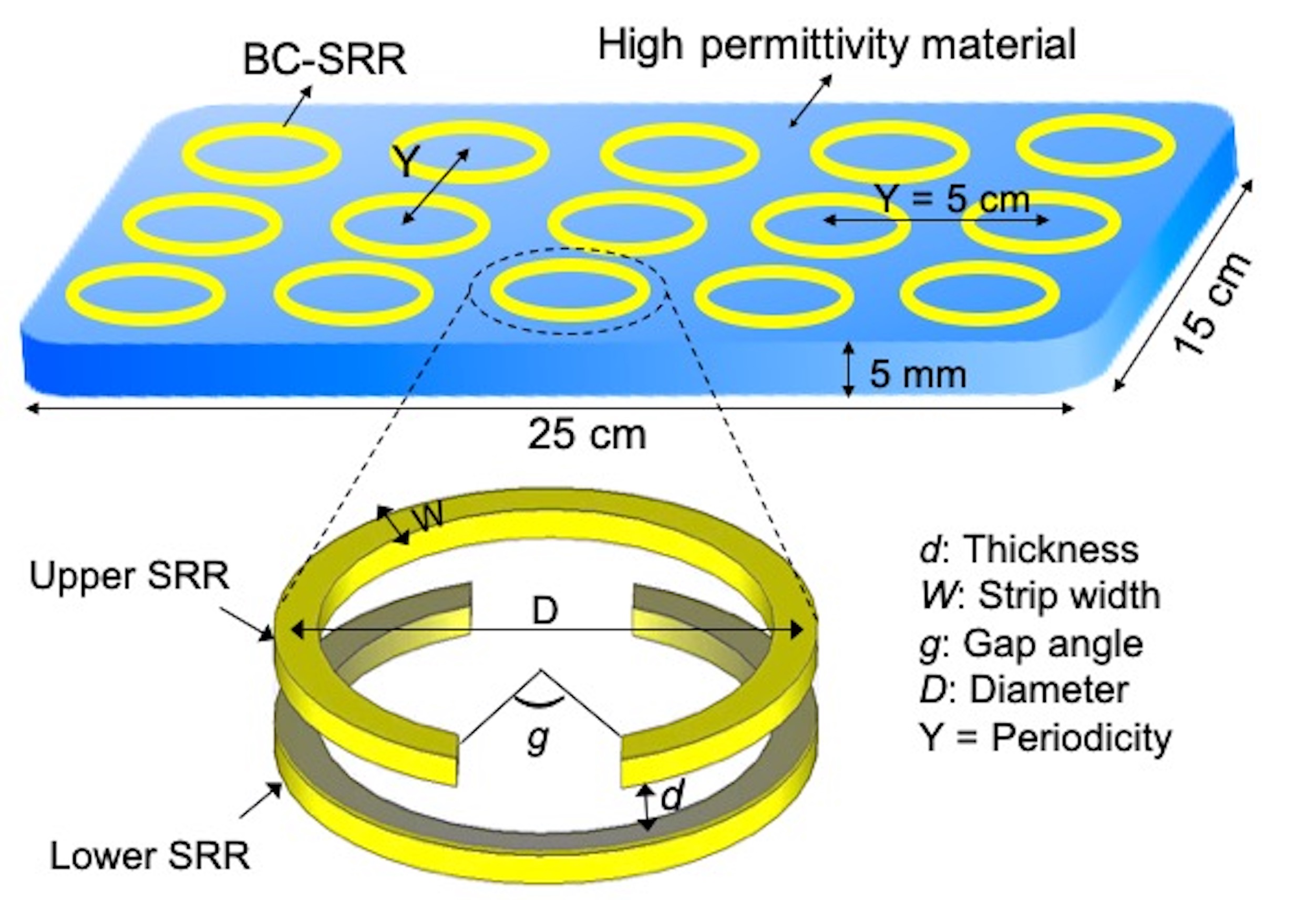
The proposed metasurface is formed of a periodic set of BC-SRRs patterned on top of a 5 mm thick HPM. Each circular BC-SRR element consists of two open conducting rings, 3.5 cm in diameter, which are etched on both sides of a flexible dielectric (Kapton) substrate, with gaps oriented in opposite positions, as shown in Figure 1. The resonators are aligned in the form of a matrix with on-center spacing of 5 cm in both directions. Elements are adjusted to operate at the Larmor frequency at 7T (297 MHz).Phantom and in-vivo images of a healthy volunteer were acquired on a 7T MRI scanner (Siemens, Magnetom, Siemens Healthcare, Erlangen, Germany) using a commercially available 1Tx/32Rx head RF coil (Nova Medical, Wilmington, MA, USA).
To assess the metasurface’s performance, $$$B_1^+$$$ and SNR maps were calculated in a phantom with/without the metasurface. $$$B_1^+$$$ maps were measured using the presaturation-prepared turbo-FLASH based method8. SNR maps were calculated using the images obtained from two GRE sequences, one with and the other without RF transmission9. SNR map was normalized by $$$B_1^+$$$ to isolate the receive sensitivity from the transmit field distribution.
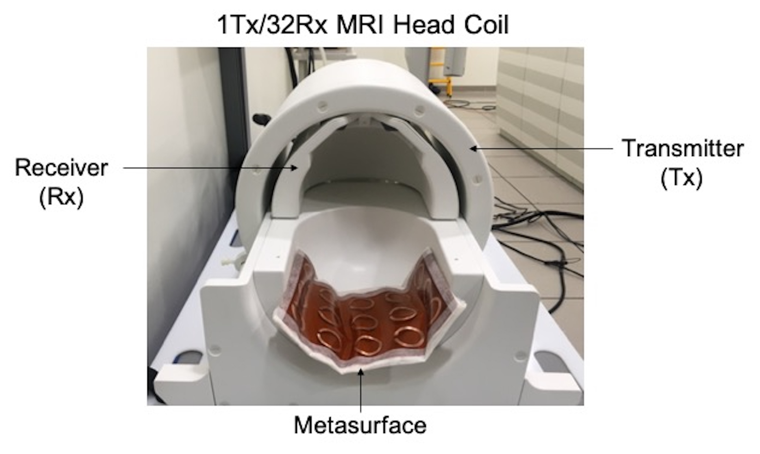
Prior to in-vivo experimentation, RF safety assessment was performed based on the ASTM method. In-vivo images were acquired in a human subject using 2D GRE (TR/TE = 500/4.3 ms, pixel resolution = 1mm 1mm, slice thickness = 2mm, flip angle =10°) and 2D TSE (TR/TE = 13,380/64 ms, pixel size = 0.7 mm 0.7 mm, slice thickness = 0.7 mm, flip angle = 160°) sequences both with and without the metasurface. Figure 2 shows the prototype of the metasurface and the position of the metasurface relative to the Nova head coil.
Results
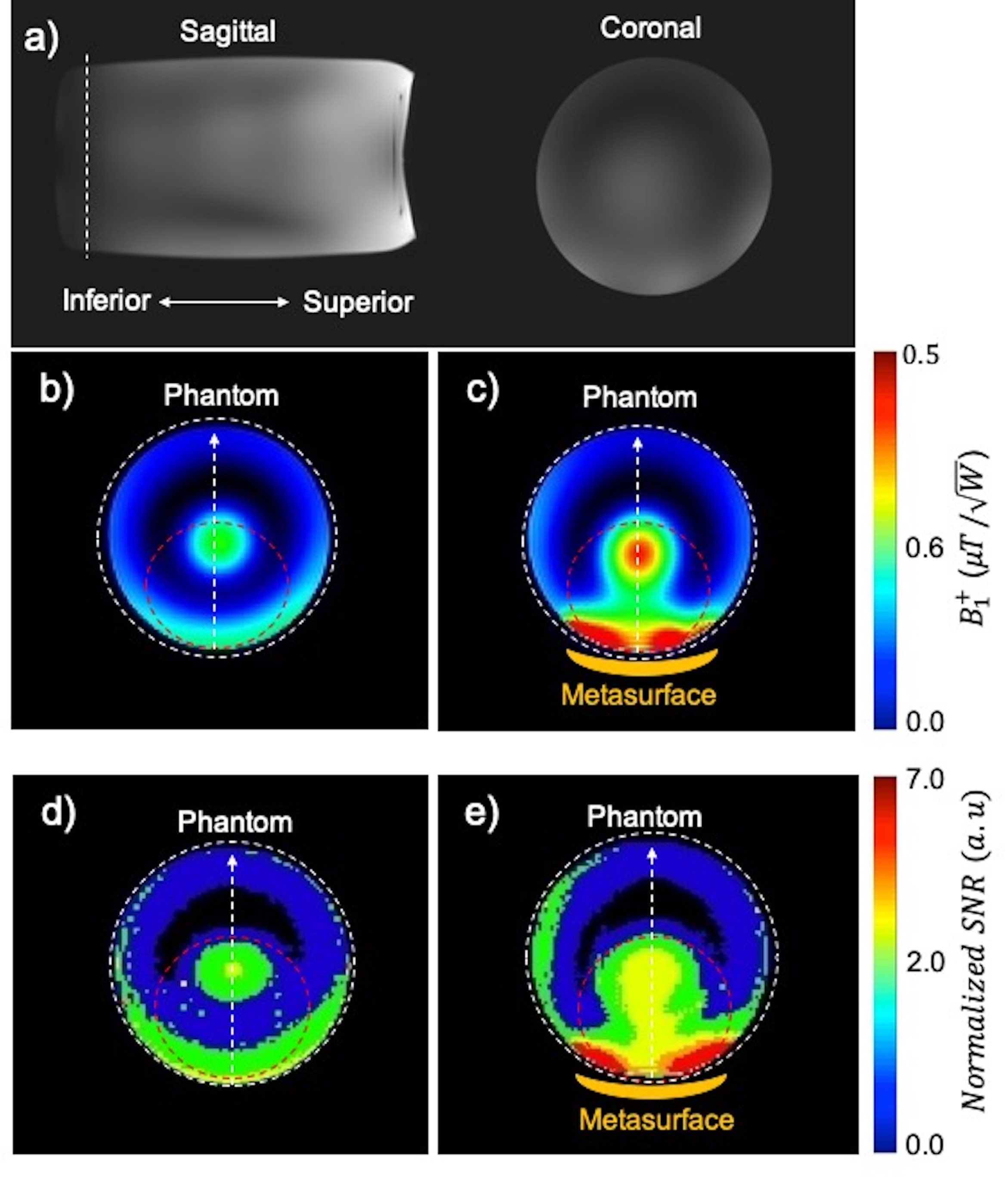
$$$B_1^+$$$ and SNR maps are displayed in the inferior region of the phantom, where the coil has a lower transmit efficiency and sensitivity (Fig. 3a). Measured $$$B_1^+$$$ maps in the phantom with/without the metasurface show placement of the metasurface inside the coil is associated with 2.1-fold increase in the transmit efficiency in the ROI encircled with dashed red (Fig. 3b, c). Experimental normalized SNR maps in the phantom with/without the metasurface show that the metasurface provides an average 1.4-fold enhancement in the ROI (Fig. 3d, e).After 15 min of RF transmission, a maximum local temperature increase of 0.44°C was recorded, while the corresponding control point showed a temperature increase of 0.35°C, corresponding to a SAR enhancement of 1.22.
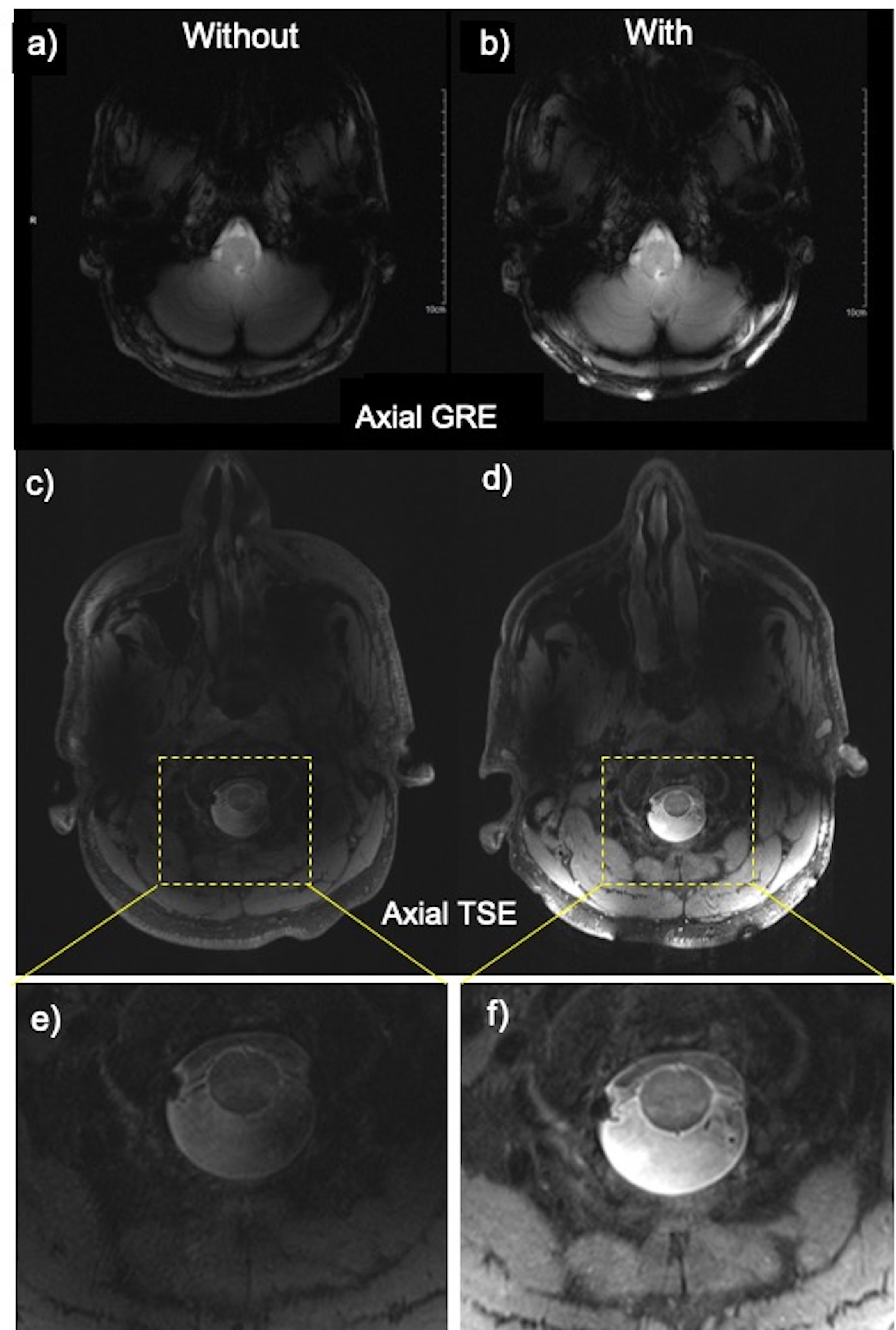
Figure 4 compares axial GRE and TSE in-vivo imaging without and with the metasurface. GRE planes (Fig. 4a,b) mostly covered the cerebellum and brainstem, while TSE planes (Fig. 4c,d) and the corresponding zoom views (Fig. 4e,f) focused on the cervical spine cord. Images obtained using the metasurface improved structural visualization by locally enhancing SNR, leading to notably improved tissue contrast. In both sequences, acceptable signal homogeneity was achieved.
Discussion and Conclusion
We have evaluated the advantages of using the metasurface in conjunction with 1Tx head coil configurations for improving visualization at 7T. Experimental safety assessments showed that local SAR at various points did not exceed current regulatory limits at the calibrated reference voltage. In-vivo imaging showed gains in transmit efficiency and signal sensitivity particularly in the posterior fossa, where structure and soft tissue contrast were improved. This increase in SNR can be leveraged to obtain a higher resolution image over the same scanning time or faster acquisition at the same resolution. This device could improve the performance of existing commercial coils at 7T for whole brain and other applications.Acknowledgements
This work was supported by an NIH grant (NIH R01CA202911). All studies involving human subjects were performed in accordance with the MRI safety review board and institutional review board of the Icahn School of Medicine at Mount Sinai.References
[1] Wu X, Auerbach EJ, Vu AT, Moeller S, Lenglet C, Schmitter S, Van de Moortele PF, Yacoub E, Uğurbil K. High-resolution whole-brain diffusion MRI at 7T using radiofrequency parallel transmission. Magn Reson Med. 2018 Nov;80(5):1857-1870.
[2] L. M. Vaidya MV, Deniz CM, et al, "Improved detection of fMRI activation in the cerebellum at 7T with dielectric pads extending the imaging region of a commercial head coil," J Magn Reson Imaging, vol. 48, no. 2, pp. 431‐440, 2018, doi: 10.1002/jmri.25936.
[3] R. Schmidt, A. Slobozhanyuk, P. Belov, and A. Webb, "Flexible and compact hybrid metasurfaces for enhanced ultra high field in vivo magnetic resonance imaging," Scientific Reports, vol. 7, no. 1, p. 1678, 2017/05/10 2017, doi: 10.1038/s41598-017-01932-9.
[4] A. Alipour et al., "Enhanced Ultra-High Field Brain MRI Using a Wireless Radiofrequency Sheet," International Society for Magnetic Resonance in Medicine, 2021.
[5] J. B. Pendry, D. Schurig, and D. R. Smith, "Controlling Electromagnetic Fields," Science, vol. 312, no. 5781, pp. 1780-1782, 2006, doi: 10.1126/science.1125907.
[6] R. R. A. Syms, I. R. Young, M. M. Ahmad, and M. Rea, "Magnetic resonance imaging using linear magneto-inductive waveguides," Journal of Applied Physics, vol. 112, no. 11, p. 114911, 2012, doi: 10.1063/1.4768281.
[7] J. M. Algarín, M. J. Freire, F. Breuer, and V. C. Behr, "Metamaterial magnetoinductive lens performance as a function of field strength," Journal of Magnetic Resonance, vol. 247, pp. 9-14, 2014/10/01/ 2014.
[8] Klose, U. (1992), Mapping of the radio frequency magnetic field with a MR snapshot FLASH technique. Med. Phys., 19: 1099-1104.
[9] Kellman, P. and McVeigh, E. R. (2005). Image reconstruction in SNR units: a general method for SNR measure- ment. Magnetic Resonance in Medicine, 54(6):1439–1447. Erratum in: Magnetic Resonance in Medicine. 2007 58(1):211—212.
Figures