0193
8-Channel Dipolectric Antenna Array for MRI at 7T: Proof-of-Principle Study in Human Brain1CIBM Center for Biomedical Imaging, Lausanne, Switzerland, 2Animal Imaging and Technology, Ecole Polytechnique Federale de Lausanne (EPFL), Lausanne, Switzerland
Synopsis
In this work we introduce a new type of antenna for ultrahigh field MRI which combines the advantages of dielectric resonator and dipole antennas: dipolectric antenna. Numerical simulations were performed to benchmark our concept against a loop-dipole antenna, and significant transmit efficiency gains in the peripheral as well as deeper located regions were observed. An 8-channel dipolectric antenna array was developed, and evaluated at the bench as well as in phantom experiments. In vivo MRI/MRS experiments at 7T were conducted and it was demonstrated that dipolectric antennas can be a promising approach for ultrahigh field MRI.
Introduction
Local multi-channel local transmit/receive (TXRX) radio frequency (RF) coil arrays are widely used in ultrahigh field MRI because they enable RF shimming and signal-to-noise ratio (SNR) gains1. Such arrays can be constructed using dielectric resonator antennas (DRA) which have some advantages over standard loop elements: DRA can be manufactured as ceramic blocks with desired dielectric constant εr and electrical conductivity σ, thereby providing an opportunity to tailor their transmit field (B1+) patterns2,3. O’Reilly et al.4 showed that a loop-coupled DRA with a very high εr (above 1000) can outperform a loop coil of similar size in terms of B1+ and SAR efficiency. The main drawback of using DRA with such high εr is the B1+ penetration depth what makes this approach limited to the peripheral regions5. To utilize this B1+ peripheral gain and still be able to reach deeper located regions without changing the electrical properties of the DRA, a different solution would be required. Dipole antennas were first proposed for MRI at 7T by Raaijmakers et al.6 who showed that high transmit efficiency in deeper located anatomical regions can be obtained. In previous work, we showed that dipole antenna can be decoupled with a loop-coupled dielectric resonator antenna7. Therefore, the goal of this proof-of-principle study was to demonstrate for the first time the feasibility of mixing loop-coupled dielectric resonator antennas with dipole antennas. For this purpose, we developed an 8-channel version of what we call dipolectric antenna (dipole + dielectric) array. The array’s performance was evaluated by means of electromagnetic field simulations, bench and MR phantom measurements. Finally, the 8-channel dipolectric antenna array was used in in vivo MRI/MRS of the human brain at 7 T.Methods
Electromagnetic field and specific absorption ratio (SAR) simulations in a spherical phantom (εr=77, σ=1.09S/m) and human voxel model “Duke” from the Virtual Family were performed using FDTD method of Sim4Life (Zurich Medtech, Switzerland). B1+ efficiency was defined as transmit field per unit power B1+/√Pin, while SAR efficiency was defined as B1+/√SAR10g where SAR10g denotes maximum SAR averaged over 10g volume. In this proof-of-principle study, a similar rectangular DRA to the one in O’Reilly et al. was used, but with a 7.5x lower σ value (εr=1070,σ=0.2S/m) enabling greater transmit field penetration depth (HyQRS,USA). To build a single-channel dipolectric antenna, DRA (90x44x5)mm3 and dipole antenna (length=250mm,width=6mm) were combined as described in Fig.1. It was driven in three different transmit (TX) modes: a) DRA-dipole TX, b) dipole-only TX (all DRA matched to 50Ω) and DRA-only TX (all dipole antennas matched to 50Ω). In each TX mode all 8 DR/dipole elements were actively receiving the signal (8-TXRX switches were used). 8-channel dipolectric antenna array (Fig.2) was developed and driven in two modes: DRA-only and dipole-only. Each TX mode (phase setting) was obtained for each array using a phase optimization algorithm8 for (Fig.2). 8-channel dipolectric antenna array was constructed and evaluated in in vivo MRI experiments using a 7-T head-only MR scanner (Siemens,Germany). B1+ mapping was performed using SA2RAGE9 (Fig.1,4). In vivo experiments were conducted: MRI using 3D-GRE sequence and MRS using short-TE STEAM (Fig.5).Results
To compare a single-channel dipolectric antenna with its loop-dipole counterpart, three different TX modes were used. Simulations revealed differences in B1+ field patterns which were confirmed by B1+ mapping experiments (Fig.1). To study the performance of 8-channel dipolectric antenna array, simulations involving Duke were conducted, and the array was benchmarked against an 8-channel loop-dipole array. It was found that coupling between DR and adjacent dipole antennas was significantly lower than loop-dipole coupling (Fig.2). Simulations showed that, depending on the TX mode, dipolectric antenna array produced: more efficient B1+ in the periphery as well at greater depths (Fig.3). To validate electromagnetic simulations, B1+ mapping in the spherical phantom was performed and a very good agreement between the simulations and measurements was observed (Fig.4). To investigate in vivo performance, the 8-channel dipolectric array was employed in MRI/MRS experiments involving one male subject (Fig.5).Discussion and Conclusion
This study demonstrates for the first time the feasibility of mixing dipole with loop-coupled rectangular dielectric resonator antennas for in vivo MRI/MRS at 7T. We showed that this approach, which we called dipolectric antenna, can benefit from all of the advantages provided by: dielectric resonator (high inter-channel isolation as well as high B1+ and SAR efficiency in the peripheral regions) and dipole antennas (high B1+ and SAR efficiency at greater depths). The 8-channel dipolectric antenna array provided substantial gains vs. the 8-channel loop-dipole array: higher B1+ and SAR efficiency in the periphery (DRA-only mode), and, interestingly, higher B1+ efficiency (dipole-only mode) not only in the periphery (since dipole antennas themselves excite TE mode), but also in deeper located regions what can be associated with lower coupling between dipole and DRA when compared with the loop-dipole case (Fig.2). Dipolectric antenna is a new approach which can be tailored for a wide range of applications: the geometry of DRA as well as its electrical properties can be optimized for either periphery or depth as well as the geometry of the dipole antenna. We conclude that dipolectric antenna array is a promising solution not only for 7T-MRI, but also for higher magnetic field strengths.Acknowledgements
We acknowledge access to the facilities and expertise of the CIBM Center for Biomedical Imaging, a Swiss research center of excellence founded and supported by Lausanne University Hospital (CHUV), University of Lausanne (UNIL), Ecole polytechnique fédérale de Lausanne (EPFL), University of Geneva (UNIGE) and Geneva University Hospitals (HUG).References
1.Ladd, et al., Progress in NMR Spectroscopy, 2018 2.Aussenhofer and Webb, MRM 2012 . 3.Aussenhofer and Webb, JMR 2014 4.O’Reilly et al., MRM 2018. 5.Wenz and Gruetter, Frontiers in Physics 2021. 6. Raaijmakers et al. MRM 2011 7. Wenz and Gruetter, ISMRM 2020. 8.Clement et al., MRM, 2019. 9.Eggenschwiler et al., MRM 2012.Figures
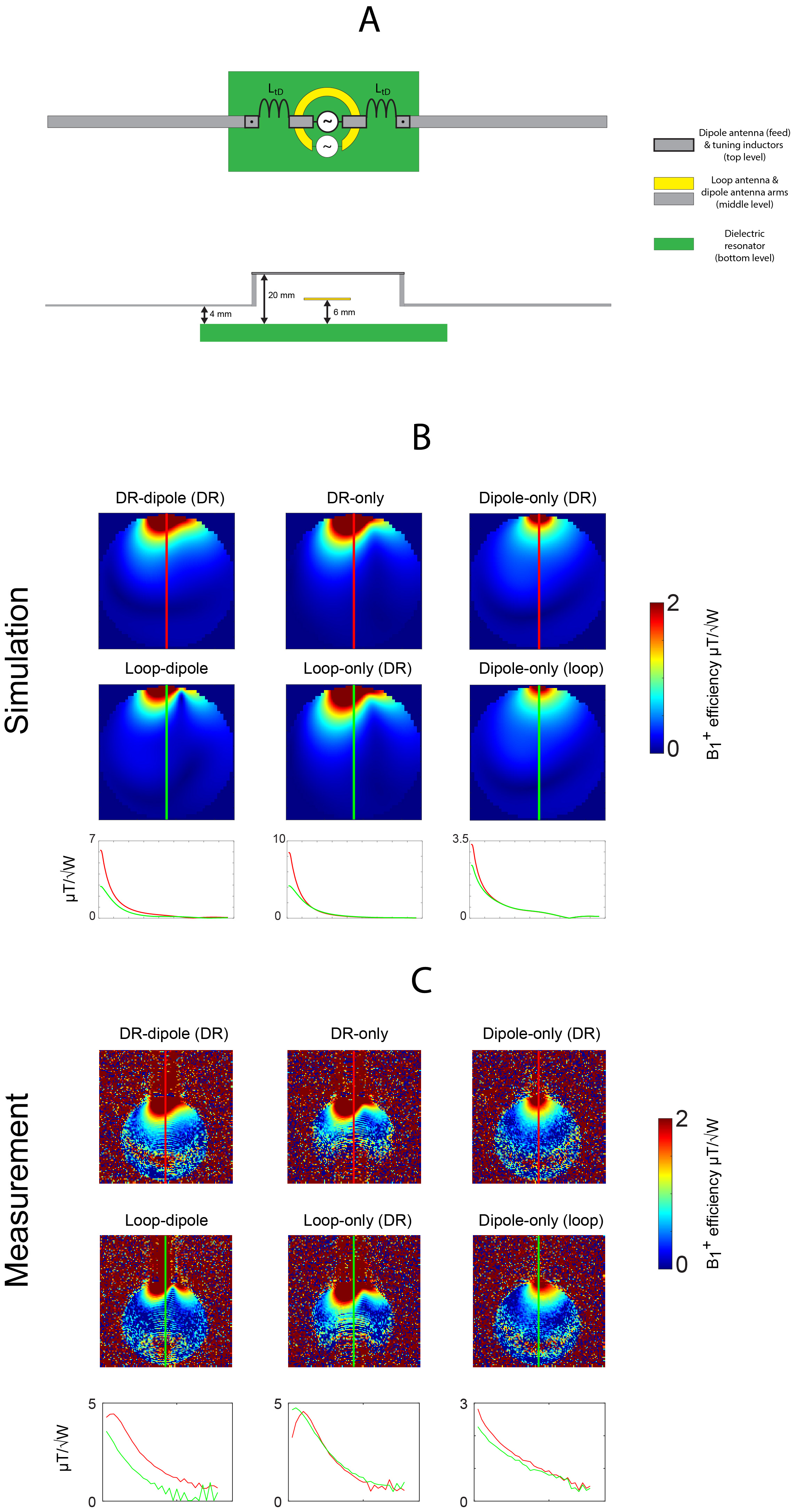
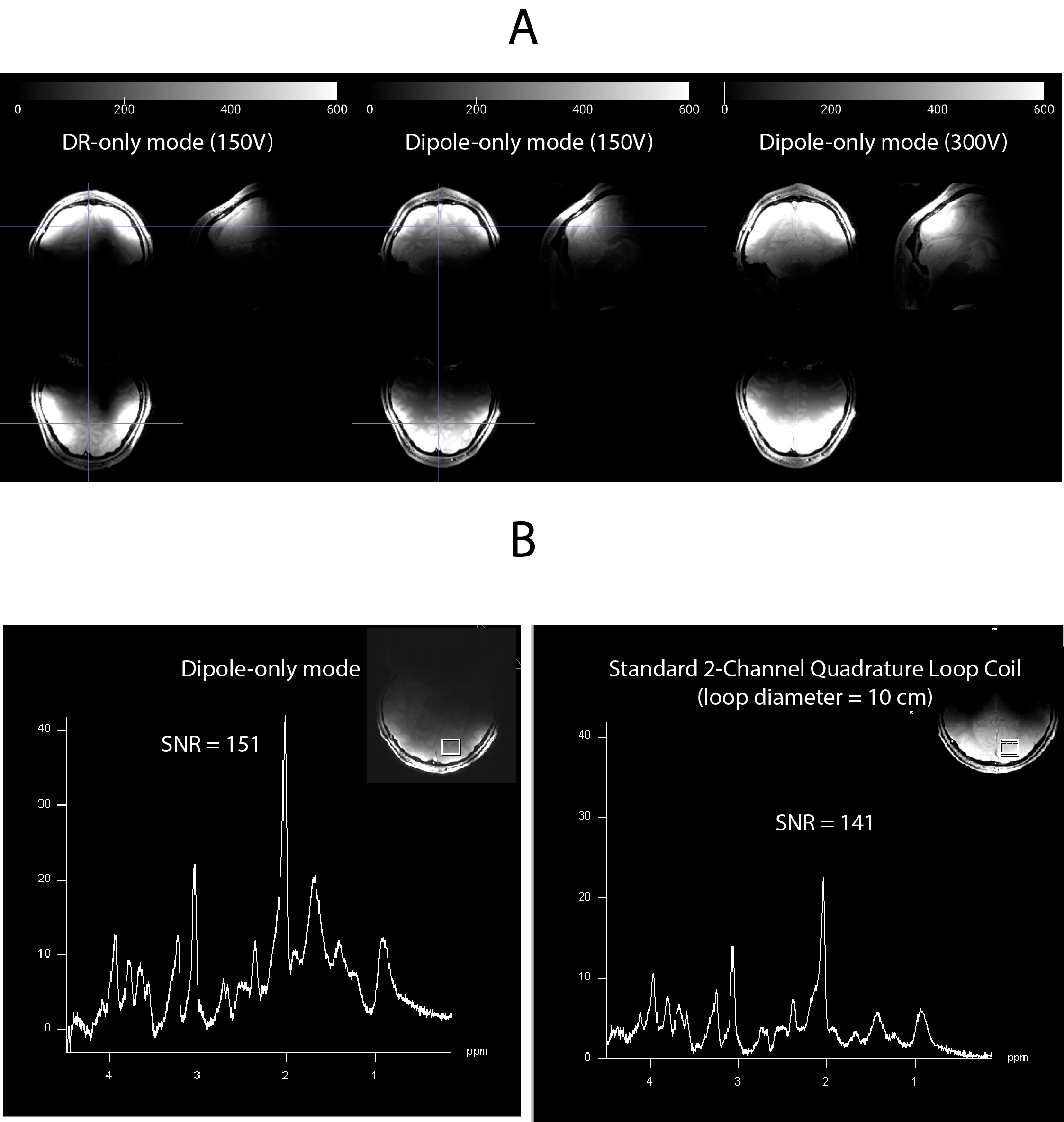
Fig. 1. A) Schematic of a single-channel dipolectric antenna (top and side view). To excite a TE mode, a small loop coil (diameter=18mm) was placed 6 mm above the block: the RF feed of the dipole antenna along with inductors were located 20mm above the top layer of the DRA. The dipole antenna’s arms were almost at the same level as the coupling loop. B) B1+ efficiency comparison with a loop-dipole antenna: simulations vs. C) measurements (in the case of DR-dipole and DR-only, transmit voltage used was too high in the phantom’s periphery).
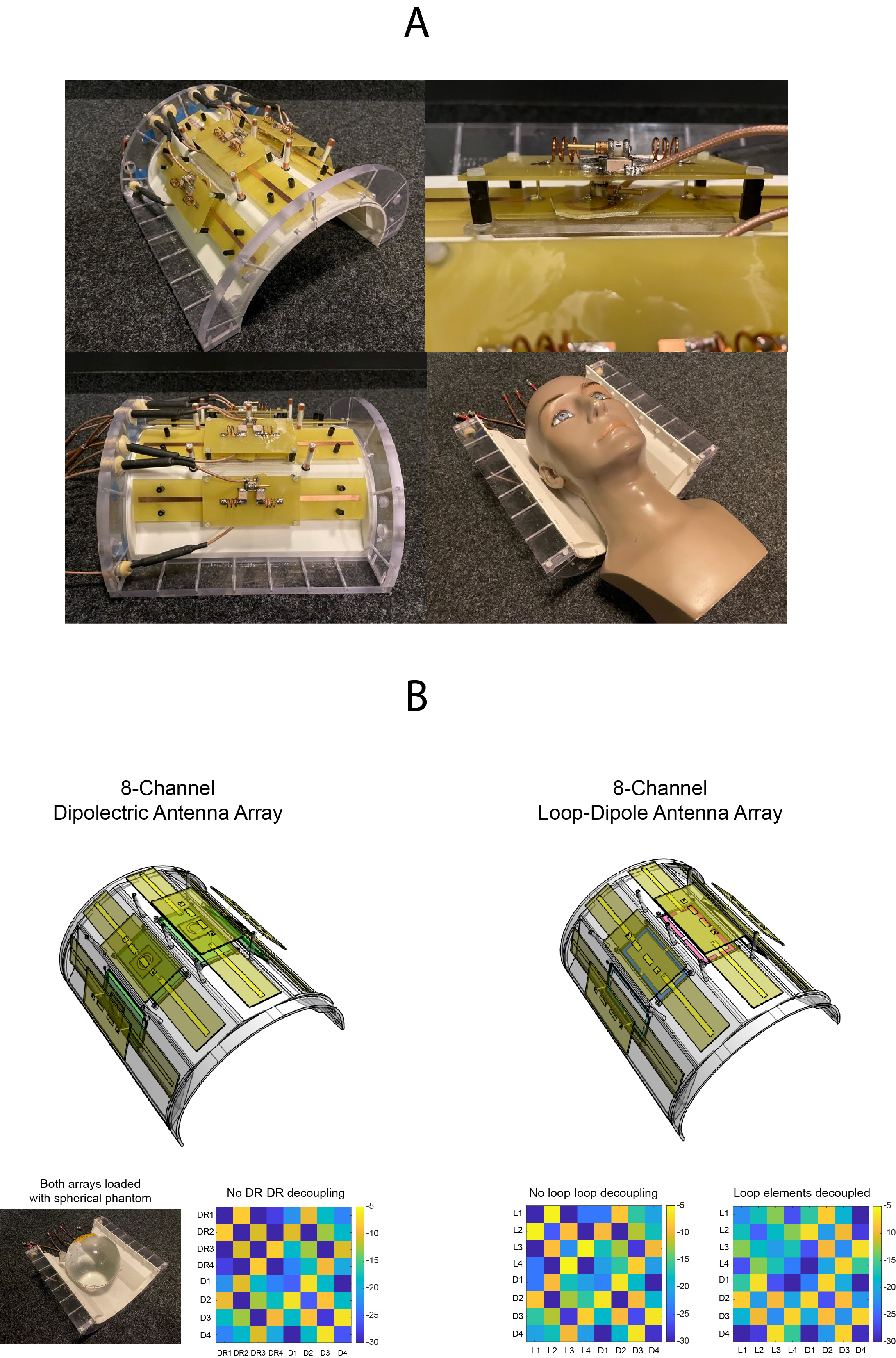
Fig. 2. A) Photographs of the 8-channel dipolectric antenna array. B) Scattering parameter matrices for the 8-channel dipolectric and 8-channel loop-dipole array. The latter is shown for two cases: before and after using additional capacitors to decouple the loop elements. This step helped to minimize loop-loop coupling, but it did not affect loop-dipole coupling which was still significantly higher than for the dipolectric antenna array. The loop-loop decoupled case was used for comparison in Fig. 3.
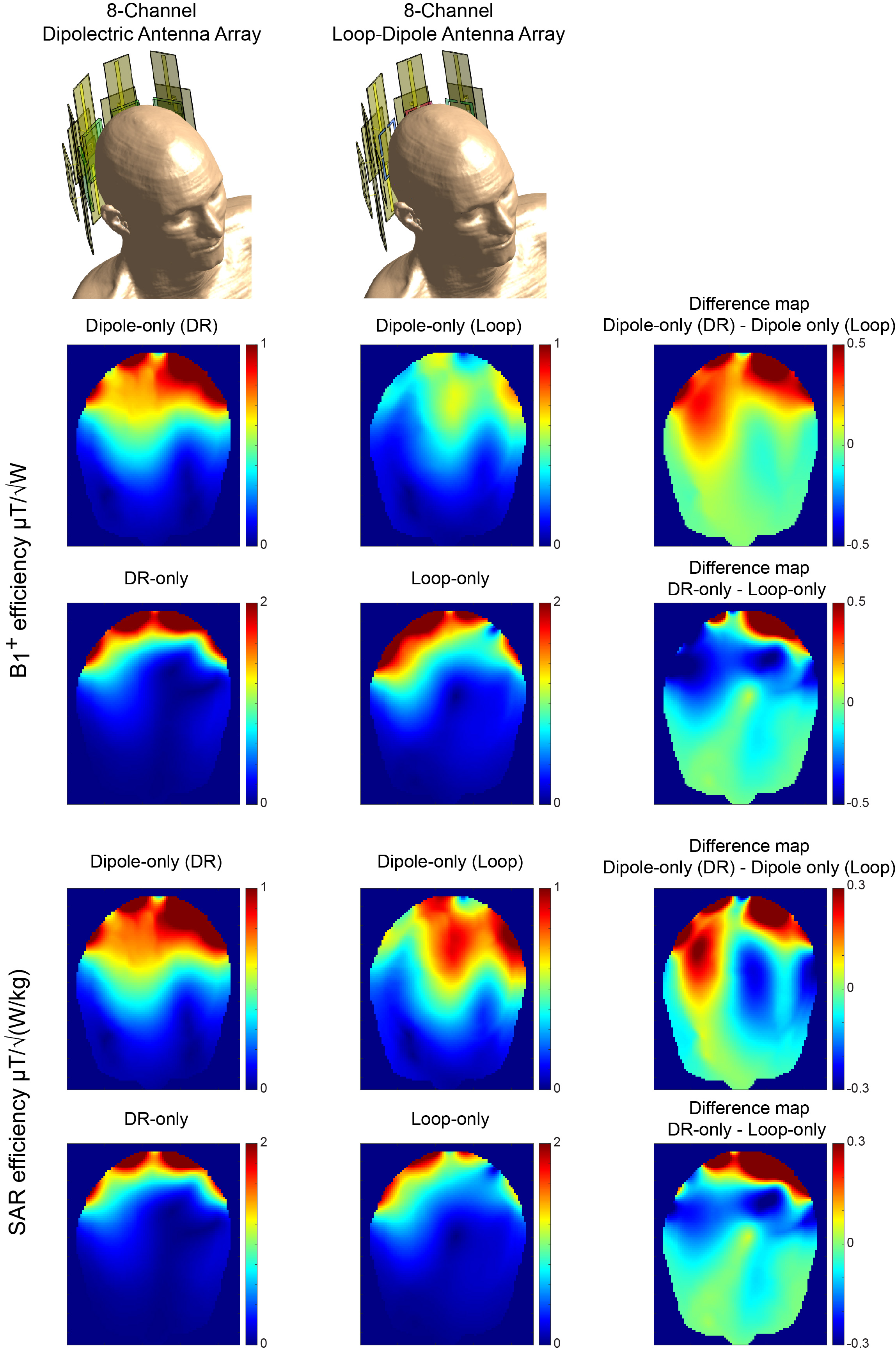
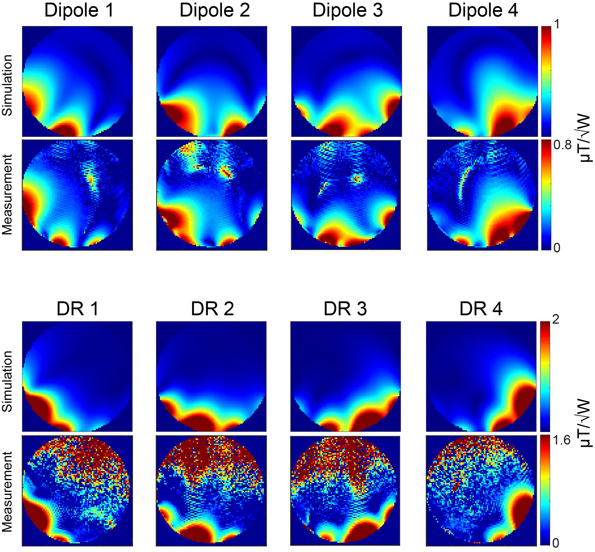
Fig. 4. Comparison of the simulated and measured B1+ fields distribution produced by each channel of the 8-channel dipolectric antenna array. SA2RAGE parmeters used: TR/TE=2400/0.78ms, FOV=256mm x 256mm, number of slices = 64, slice thickness = 2.5mm.