0192
On-coil digitization with a 130nm CMOS receiver: Electromagnetic compatibility and use for a wearable knee array1Institute for Biomedical Engineering, ETH Zurich and University of Zurich, Zurich, Switzerland, 2Integrated Systems Laboratory, ETH Zurich, Zurich, Switzerland
Synopsis
The relevant electromagnetic compatibility mechanisms of an integrated receiver based on 130nm CMOS technology are investigated. Imaging performance is verified with a digital wearable array, which was based on liquid metal and layed out for knee imaging. The study found that gradient switching and transients related to detuning are not critical in terms of EMC. However, coupling of RF to the preamplifier input has been found to exceed the receiver’s acceptable input voltage of 1.7V despite the use of protection diodes. Thus, a B1 limitation was applied and robust imaging performance was demonstrated in phantom and in vivo imaging.
Introduction
Wearable arrays1–5 deliver high sensitivity, patient comfort and enable kinematic studies of joints. Their cabling, however, is a limiting factor in terms of handling, image quality and patient safety. To address this drawback current efforts aim to move digitization of MR signals on coil for subsequent optical signal transmission. For small size and low power consumption such digitization has recently been included in an integrated receiver based on 130nm CMOS technology6,7. However, this comes at the cost of low voltage handling capability (max. +-1.7V on RF inputs) and thus vulnerability to RF transmission, gradient switching and other voltage transients e.g. detune switch event (Figure 1).In this work, we investigate the relevant electromagnetic compatibility (EMC) mechanisms. We then verify imaging performance with a digital wearable array, which was based on liquid metal and layed out for knee imaging including bending of the joint.
Methods
Transient simulations were performed in ADS (Keysight Technologies, Santa Rosa, CA, USA). Occurring voltages at the receiver inputs were simulated for RF transmission, gradient switching and detune switch events (Figure 2a). RF and gradients were modeled as signal sources, while the detune switch event was modeled as a voltage step.In-bore measurements were performed in a 3T Philips Ingenia system (Philips, Amsterdam, Netherlands). For oscilloscope measurements of the voltages that would occur on the receiver’s inputs during imaging, an 8x8cm coil with matching and detuning was placed on a phantom and a resistor network was plugged into the coil ports. This resistor network mimicked the receiver’s input impedance and was connected to the oscilloscope through coaxial cable.
The receiver’s preamplifier is the most critical element in terms of EMC. For this reason, a duplicate of the receiver’s integrated preamplifier was designed and manufactured in the same 130nm CMOS technology. This stand-alone preamplifier was used in an SNR comparison to a reference preamplifier module1.
Phantom images were acquired using the 8x8cm coil (Figure 4a) and a two-channel liquid metal array, with a coil element size of 6x16cm (Figure 4b). Coils were connected to the receiver for on-coil digitization and a custom platform was used for digital data acquisition and storage8,9.
A wearable liquid metal array (Figure 5) was built from stretchable textile4,5. Sagittal in vivo images at two different flexion angles of a volunteer’s knee were acquired with the data digitized on-coil. Images were corrected for sensitivity variation.10
Results
The receiver has a voltage limit of +-1.7V on its RF inputs. Figure 2 shows that the simulated voltage on the receiver inputs with protection diodes due to gradient switching amounts to 110mV. This is well below the voltage limit and was even lower in the in-bore measurement. The voltages due to detune switch events were 160mV and 170mV, which is in good agreement with the measured value of 170mV. In the case of RF transmission, however, simulations predicted a maximum voltage of 0.76V for a B1 of 13.5uT, but the corresponding measurement was 8V. Hence, we reduced B1 for the rest of the study to a value of 1uT, which resulted in a voltage of 1.5V for the 8x8cm coil, which is compatible with the receiver RF inputs. For the slightly larger liquid metal array, B1 was limited to 0.7uT.The stand-alone preamplifier yielded 94.2 % of the SNR of the commercial reference preamplifier (Figure 3).
Figure 4 shows the acquired phantom images, which are free from artifacts, such as RF spurs or an elevated noise floor.
In vivo images (Figure 5) demonstrate good sensitivity and coverage of the coil array. High SNR is achieved in the top of the knee where the coil elements reside and are most sensitive. The patella and cruciate ligaments are readily visible.
Discussion
This study found that for a receiver in 130nm CMOS, gradient switching and transients related to detuning are not critical in terms of EMC. However, coupling of RF to the preamplifier input has been found to exceed the low threshold of 1.7V despite the use of protection diodes. In fact, the perturbation measured significantly exceeded the results of circuit simulation. One path forward is thus to review the protection strategy and improve detuning isolation. The more versatile solution would be to implement the preamplifier in a transistor technology with higher voltage handling capability, albeit at the cost of higher power consumption. Based on the aforementioned issue, the remainder of the study has been performed at limited B1 for safe operation. In this regime, SNR decreased by only 5.8% for the stand-alone preamplifier relative to the reference preamplifier (Figure 3). Phantom (Figure 4) as well as in vivo imaging (Figure 5) demonstrate robust operation and imaging performance of the CMOS receiver. Images display sensitivity variation, which is typical for surface coils and could be resolved by employing a higher number of receive channels surrounding the knee4,5. Notably, geometric reconfiguration upon bending did not impair image quality indicating sufficient margin with respect to all three potential EMC concerns. The proposed digital wearable array streams MR data using an optical link. Galvanic connections for power and detuning remain. Towards fully non-galvanic or even wireless arrays11 wireless power transfer12 and detuning13 could be employed.Acknowledgements
No acknowledgement found.References
1. Nordmeyer-Massner JA, De Zanche N, Pruessmann KP. Stretchable coil arrays: Application to knee imaging under varying flexion angles. Magn Reson Med. 2012;67(3):872-879. doi:10.1002/mrm.23240
2. Zhang B, Sodickson DK, Cloos MA. A high-impedance detector-array glove for magnetic resonance imaging of the hand. Nat Biomed Eng. 2018;2:570-577. doi:10.1038/s41551-018-0233-y
3. Vincent JM, Rispoli J V. Conductive thread-based stretchable and flexible radiofrequency coils for magnetic resonance imaging. IEEE Trans Biomed Eng. 2020;67(8):2187-2193. doi:10.1109/TBME.2019.2956682
4. Port A, Luechinger R, Albisetti L, et al. Detector clothes for MRI: A wearable array receiver based on liquid metal in elastic tubes. Sci Rep. 2020;10:8844. doi:10.1038/s41598-020-65634-5
5. Port A, Luechinger R, Brunner DO, Pruessmann KP. Elastomer coils for wearable MR detection. Magn Reson Med. 2021;85(5):2882-2891. doi:10.1002/mrm.28662
6. Sporrer B, Wu L, Bettini L, et al. A fully integrated dual-channel on-coil CMOS receiver for array coils in 1.5-10.5 T MRI. IEEE Trans Biomed Circuits Syst. 2017;11(6):1245-1255. doi:10.1109/TBCAS.2017.2764443
7. Port A, Reber J, Vogt C, et al. Towards wearable MR detection: A stretchable wrist array with on-body digitization. In: Proceedings of the 26th Annual Meeting of ISMRM, Paris, France, 2018. p. 0017.
8. Marjanovic J, Reber J, Brunner DO, et al. A Reconfigurable Platform for Magnetic Resonance Data Acquisition and Processing. IEEE Trans Med Imaging. 2020;39(4):1138-1148. doi:10.1109/TMI.2019.2944696
9. Reber J, Marjanovic J, Brunner DO, et al. An In-bore Receiver for Magnetic Resonance Imaging. IEEE Trans Med Imaging. 2020;39(4):1-1. doi:10.1109/tmi.2019.2939090
10. Wallner BK, Edelman RR, Bajakian RL, Kleefield J, Atkinson DJ, Mattle HP. Signal normalization in surface-coil MR imaging. Am J Neuroradiol. 1990;11(6):1271-1272.
11. Nohava L, Ginefri J, Willoquet G, Laistler E, Frass-Kriegl R. Perspectives in Wireless Radio Frequency Coil Development for Magnetic Resonance Imaging. Front Phys. 2020;8:11. doi:10.3389/fphy.2020.00011
12. Byron K, Winkler SA, Robb F, Vasanawala S, Pauly J, Scott G. An MRI compatible RF MEMs controlled wireless power transfer system. IEEE Trans Microw Theory Tech. 2019;67(5):1717-1726. doi:10.1109/TMTT.2019.2902554
13. Lu JY, Robb F, Pauly J, Scott G. Wireless Q-spoiling of receive coils at 1.5T MRI. In: Proceedings of the 25th Annual Meeting of ISMRM, Honolulu, USA, 2017. p. 4297.
Figures
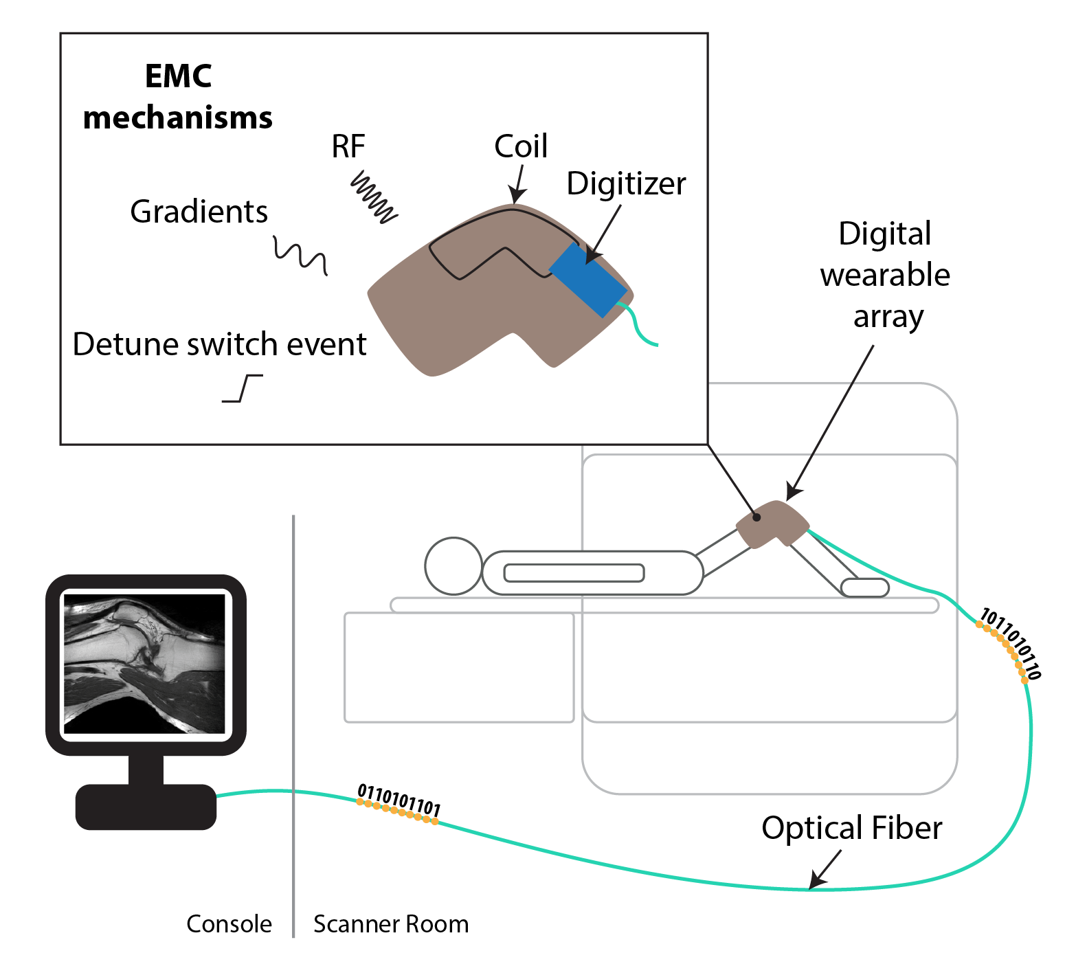
On-body digitization. The digitizer is implemented in 130nm CMOS technology, which allows for small size and low power consumption. However, this also makes it vulnerable to interference from RF transmission, gradient switching and detune switch events.
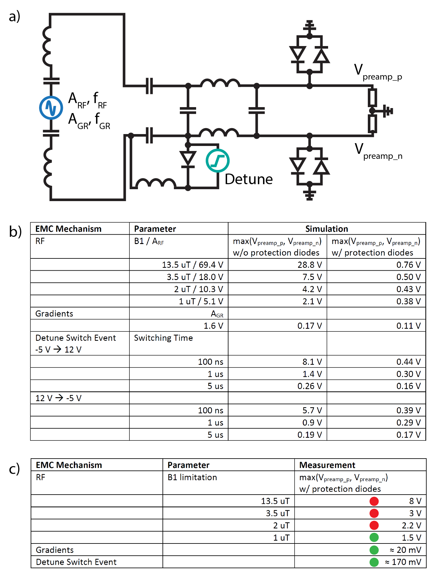
Simulation/measurement setup. The coil size was 8x8cm for the simulations and measurements. a) RF and gradient frequencies were fRF=127.8MHz and fGR=10kHz. The amplitudes ARF and AGR corresponded to the EMF induced in the coil depending on B1 values for RF and on a gradient strength of 40mT/m and distance of 10cm from the isocenter for gradients. The detune switch event was modeled as a voltage step. The simulated voltages on the receiver’s RF inputs were Vpreamp_p and Vpreamp_n. b) Simulation results for the three EMC mechanisms. c) Results for in-bore measurements of voltages.
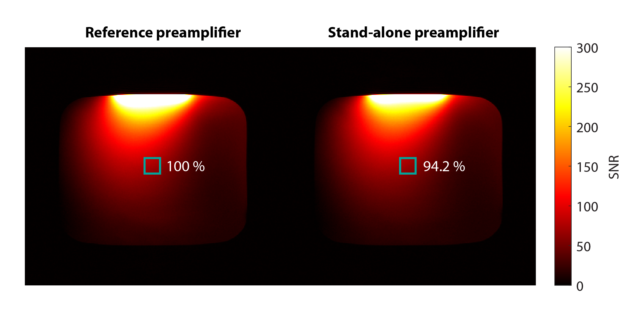
SNR comparison between reference and stand-alone preamplifier. Each preamplifier was connected to an 8x8cm coil, which was individually tuned and noise matched. SNR yield was determined in a region-of-interest in the center of the phantom.
Imaging sequence parameters: TR 30ms, TE 6.1ms, FA 30°, 1x1x10mm3, FOV 280x280mm, Scan duration 0:24min.
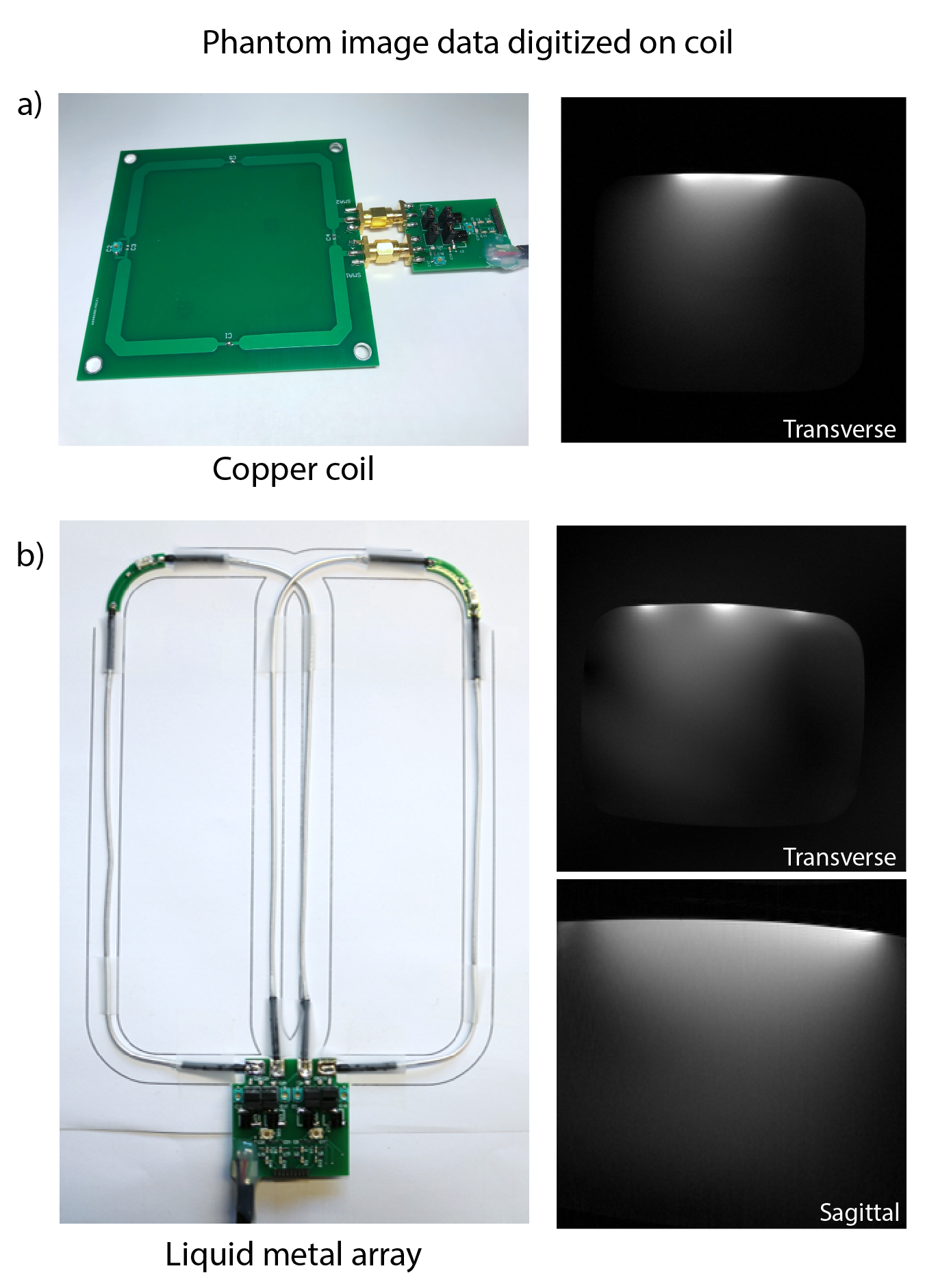
Phantom imaging with on-coil digitization. a) The 8x8cm copper coil had a Q-ratio of Qunloaded/Qloaded = 322/20 = 16.1. Imaging sequence parameters: TR 30ms, TE 6.1ms, FA 30°, 1x1x10mm3, FOV 280x280mm, Scan duration 0:09min. b) The coil elements of the liquid metal array were sized 6x16cm and had Q-ratios of Qunloaded/Qloaded = 120/17 = 7.1 and Qunloaded/Qloaded = 135/17 = 7.9. Imaging sequence parameters: TR 30ms, TE 6.9ms, FA 30°, 1x1x10mm, FOV 280x280mm, Scan time 0:09min (Transverse) and TR 500ms, TE 6.4ms, FA 30°, 1x1x3mm3, FOV 200x200mm, NSA 2, Scan time 3:22min (Sagittal).
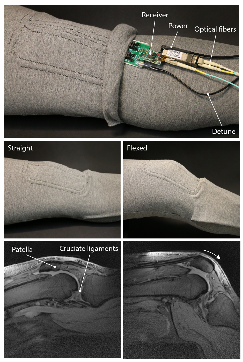
The digital wearable array. Liquid metal coil elements were embedded between two layers of stretchable textile. Interface electronics for tuning, matching and detuning as well as the receiver are connected to the coil. Acquired MR data is sent out of the bore via optical fibers. In vivo images were acquired in straight and flexed position. Imaging sequence parameters:
TR 500ms, TE 6.2ms, FA 30°, 1x1x3mm3, 10 slices, Scan duration 3:22min, 2 NSA, FOV 200x200x33 (Straight) and TR 500ms, TE 6.3ms, FA 30°, 1x1x3mm3, 10 slices, Scan duration 3:22min, 2 NSA, FOV 200x200x33 (Flexed).