0191
ModFlex – a modular system of flexible receive-only coil arrays for 3 T MRI1High Field MR Center, Center for Medical Physics and Biomedical Engineering, Medical University of Vienna, Vienna, Austria, 2IADI, Inserm, Université de Lorraine, Nancy, France, 3Laboratoire d’Imagerie Biomédicale Multimodale Paris Saclay (BioMaps), CEA, CNRS, Inserm, Université Paris-Saclay, Orsay, France, 4CHRU-Nancy, Inserm, Université de Lorraine, CIC, Innovation Technologique, Nancy, France
Synopsis
Flexible form-fitting radiofrequency coils provide high signal-to-noise ratio during MRI, and in array configuration large anatomical areas of interest can be covered. We propose a modular system - “ModFlex”- of flexible lightweight 4-channel coaxial coil arrays for 3T MRI. We investigated the performance difference between commercial reference coils and 8- and 16-channel ModFlex receive-only array systems. The versatility of ModFlex, the robustness of the coil characteristics for different use cases and a signal-to-noise gain compared to reference coils is demonstrated.
Introduction
Radiofrequency (RF) coil arrays optimizing the signal-to-noise ratio (SNR) in magnetic resonance imaging (MRI) have a form-fitting design where the size of both, the overall array and the individual elements, is adapted to the target anatomy. In this context, we developed a modular system - “ModFlex”- of flexible lightweight 4-channel coaxial RF coil arrays1 for 3T MRI. The goal was to provide a versatile solution for a customized assembly of surface coil arrays allowing for a field-of-view (FOV) coverage tailored to the application, enhanced image quality, a faster imaging workflow and improved patient comfort. The flexible coaxial coil array design and key-concept of modularity has been examined in previous work2. Here, we present the hardware implementation, first bench and phantom MR measurements of a ModFlex system with up to 16 Rx-channels for different use cases, and an SNR comparison to commercial reference coils at 3T.Materials and Methods
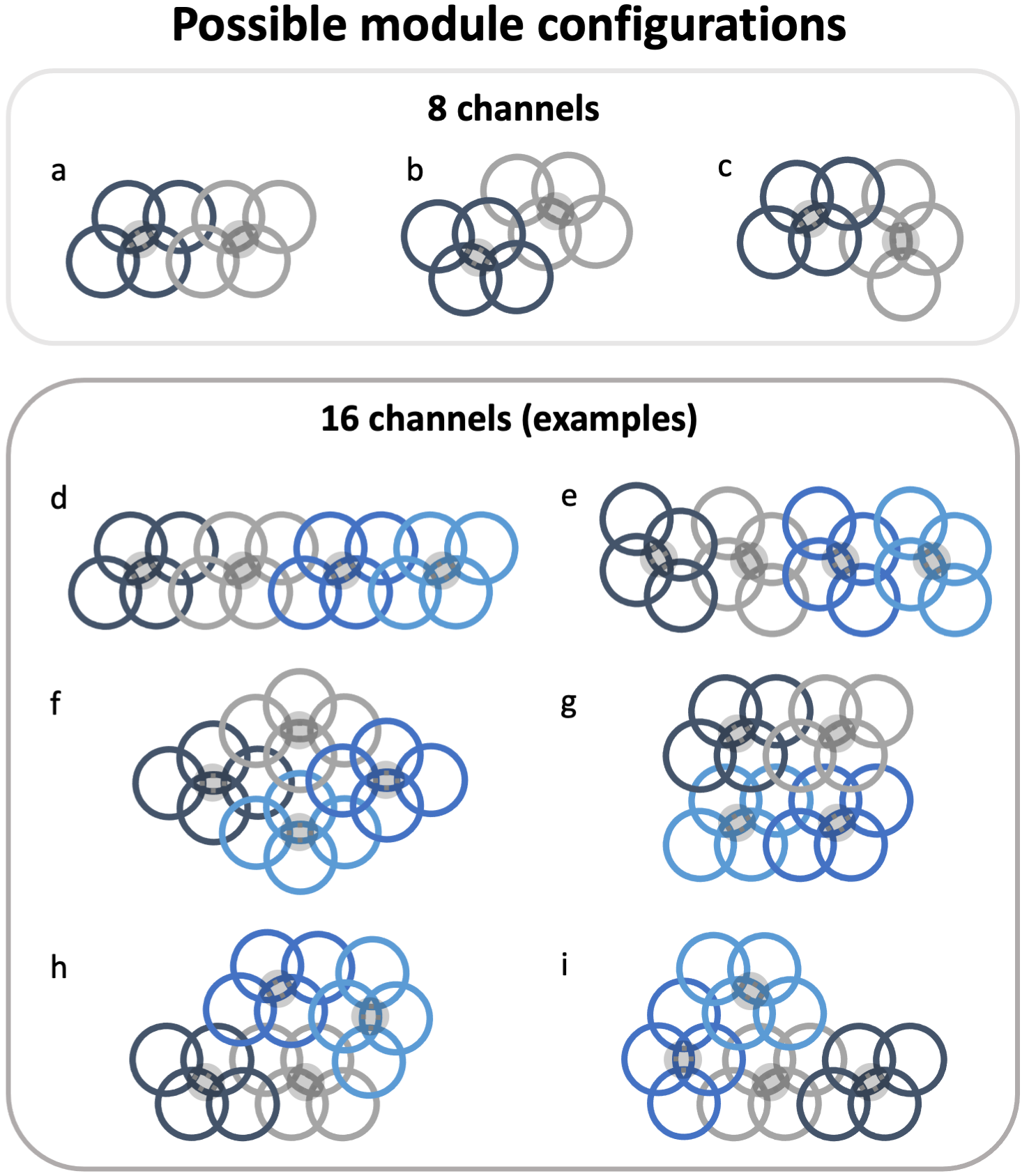
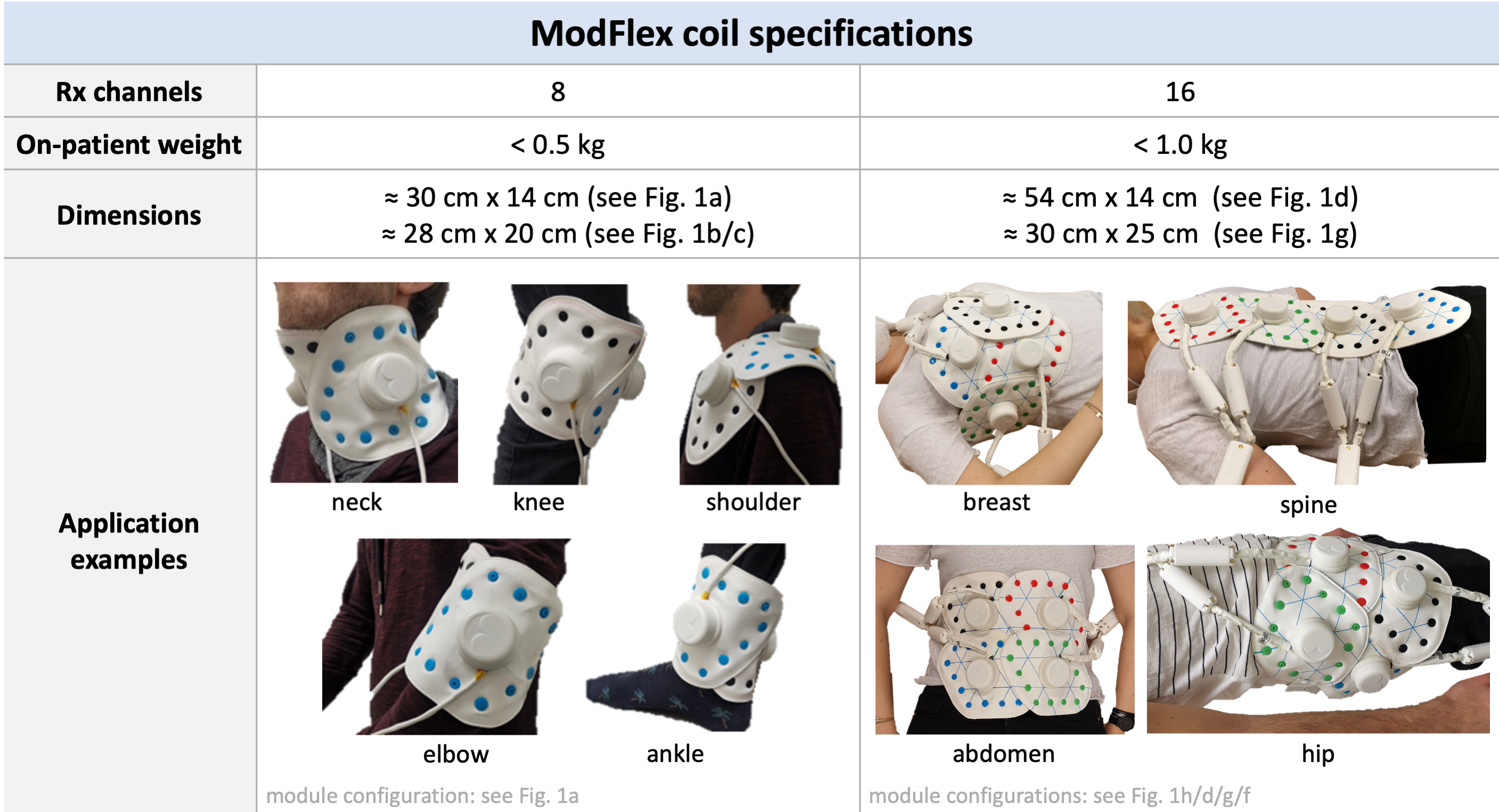
Coil featuresFig.1 shows an 8-channel ModFlex consisting of two individual 4-channel coil modules. Four flexible single-gap coaxial coils3,4 (8cm diameter) are embedded in three textile layers. A compact housing holds all necessary electrical components for tuning, matching, active detuning, preamplifier decoupling and on-coil low-noise preamplification. One floating shield current suppression trap5 (>25dB attenuation at 123.2MHz) is placed on each module’s cable strand which is then routed to a Y-connection, linking the two modules to the MR system cable. Individual modules can be connected via plastic snap buttons in different possible configurations (see Fig.2). Button colors enable the identification of all modules at the MR console and (de-)activation of those needed to image the desired FOV. In Fig.3 relevant ModFlex coil specifications and some application examples for 8/16-channel use cases are summarized. The on-patient weight of <0.5kg per 8-channel coil array ensures patient comfort and convenient coil handling.
Bench and MR measurements
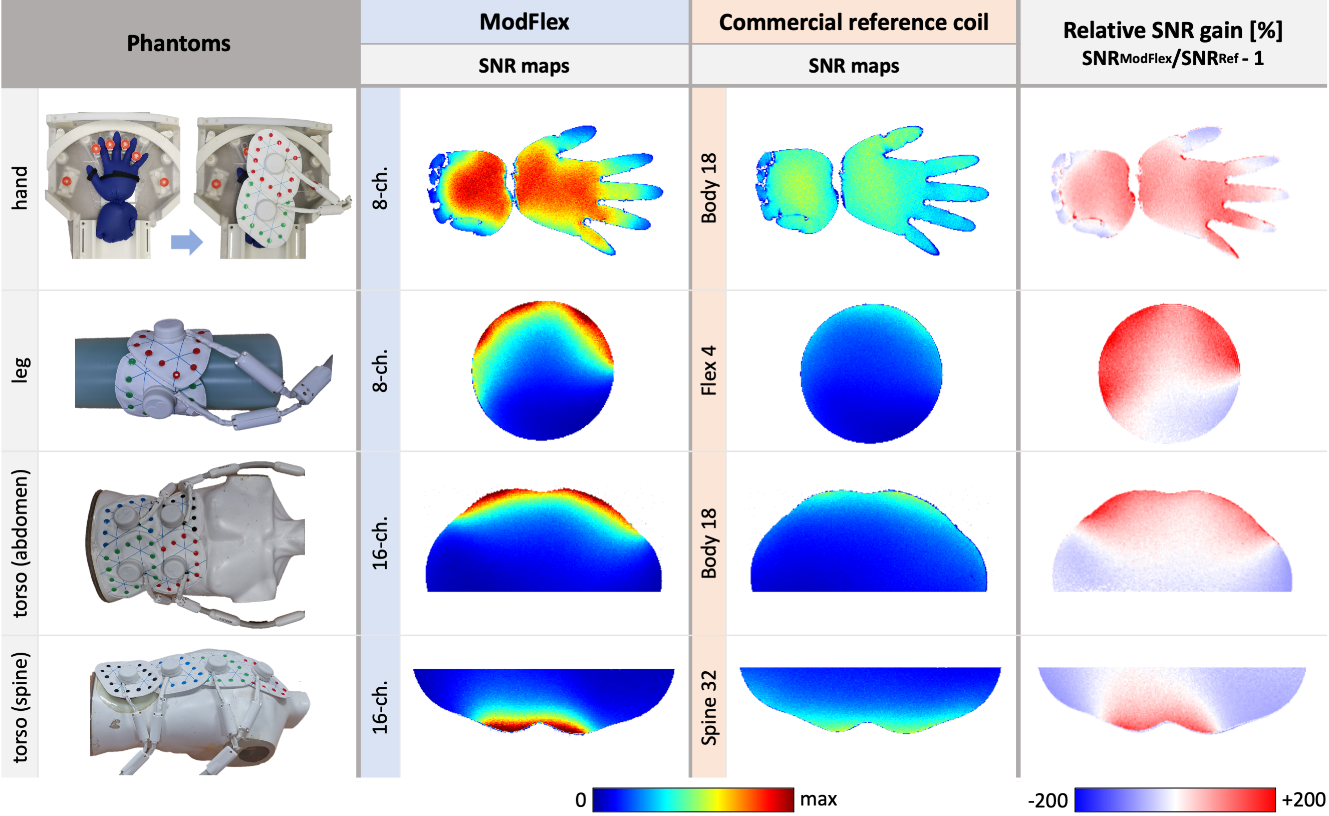
During bench and MR tests, different phantoms (see Fig.4, left column) were used: 1) a hand phantom (two saline-filled gloves, 5g/l NaCl, 279.32 mg/l Gadoteric acid), 2) a leg phantom (cylindric commercial phantom, d=15cm, 5.3l volume, 3.75g NiSO4 x 6H20 + 5g NaCl), and 3) a torso phantom filled with gel mimicking tissue electrical properties (σ= 0.60S/m, ε=62).
Bench tests were performed with a vector network analyzer (E5071C, Keysight Technologies, Santa Rosa, USA). S-parameters were measured in different 8/16-channel configurations (see caption Fig.2) to determine matching levels and overlap decoupling efficiency. A dual-loop probe6 was used to characterize the active detuning and preamplifier decoupling performance.
MR experiments were carried out on a 3T MR scanner (Prisma Fit, Siemens Healthineers, Erlangen, Germany). ModFlex was directly placed or wrapped around the phantom (see Fig.4, left column). The commercial reference coils (Flex 4/Body 18/Spine 32, Siemens Healthineers, Erlangen, Germany) for SNR comparison were either chosen because of the specific setup requirements (dynamic hand imaging) or a similar FOV coverage and coil element size (leg, spine, abdomen imaging). 2D gradient echo (GRE) images were acquired in a central coronal (hand phantom) or transversal slice (leg and torso phantom). The FOV was adapted depending on the phantom size to yield 1x1mm2 in-plane resolution (FA=25°, TR/TE=100/10ms for hand/leg, TR/TE=100/3.82ms for torso phantom, 3mm slice thickness). In post-processing, SNR maps were calculated7 from 2D GRE acquisitions and noise only scans.
Results and Discussion
Bench measurementsS-parameters in the 8-channel configurations indicated a mean matching level of -20.9dB (max. -13.7dB) and mean geometric decoupling of -24.6dB (max. -14.0dB). In the 16-channel configurations of Fig.2d+g the mean matching was -18.7dB (max. -10.3dB) and mean geometric decoupling -31.2dB (max. -13.5dB).
The measured ΔS21 between tuned and detuned state was >25.0dB and the preamplifier decoupling efficiency was >11.4dB.
MR experiments
Phantom MR experiment results shown in Fig.4 demonstrate an SNR gain in the target FOV with ModFlex compared to the commercial reference coils. High local SNR close to the coil conductors, typical for surface coil arrays, can be observed. The 8cm coil elements achieve less penetration depth8 than larger elements in the reference coils which could be compensated by combining more than one 16-channel ModFlex, e.g. wrapped around at the back for abdomen imaging.
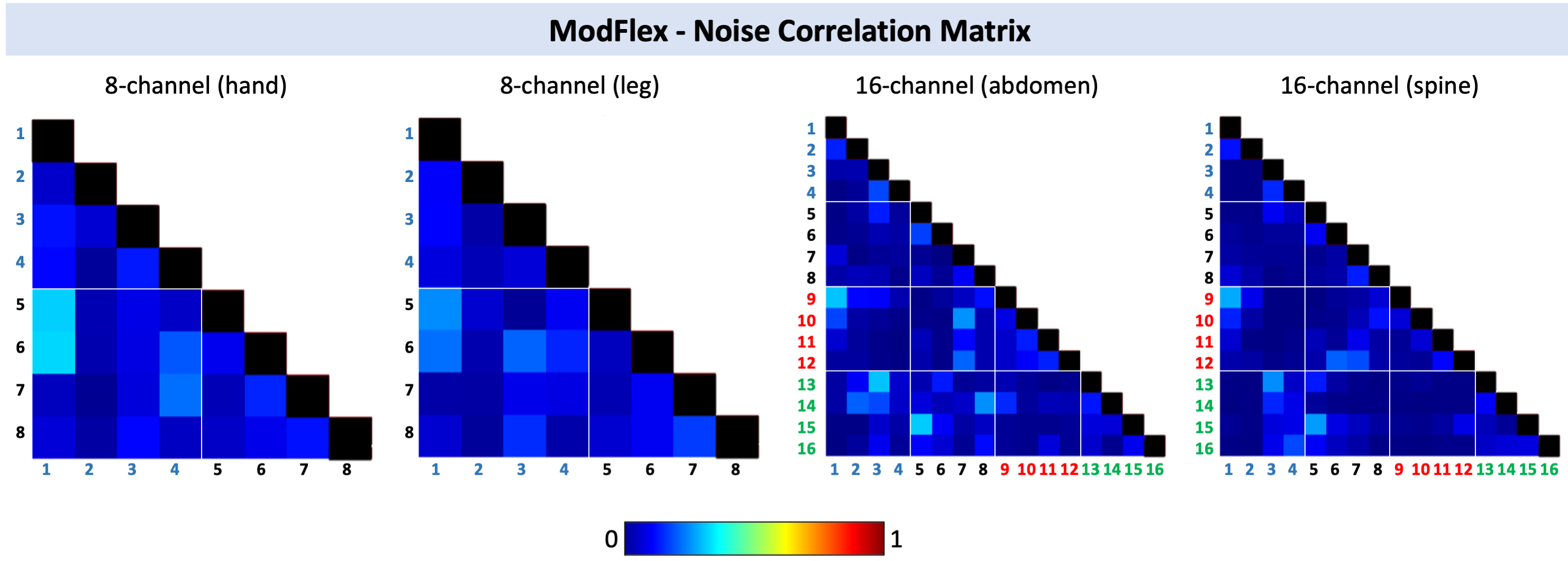
Normalized noise correlation values between coil elements are shown in Fig.5 for 8-channel measurements (0.33 maximum, mean 0.11), and 16-channel measurements (0.32 maximum, mean 0.06).
Conclusion
In conclusion, we studied a flexible modular coil array concept - “ModFlex” - characterized by its broad range of possible applications thanks to its modularity and high flexibility, improved SNR compared to reference coils, a more convenient coil setup and patient comfort. In clinical practice, ModFlex is also a versatile tool for niche applications where no dedicated coils are available. Furthermore, the one-system-for-all principle especially benefits sites with limited coil equipment and is useful in studies on anatomical areas with large inter-patient variability. Future work will involve in vivo measurements, parallel imaging performance evaluation and hardware optimization, e.g. a system plug reduction, and the inclusion of additional on-coil sensors.Acknowledgements
This work was funded by a joint Austrian/French grant (Austrian Science Fund FWF Nr. I-3618/Agence Nationale de Recherche ANR-17-CE19-0022) “BRACOIL“.References
2. Obermann, M., Roat, S. & Laistler, E. Coaxial coil modules as building blocks of individually arranged receive-only coil arrays. in Proc. Intl. Soc. Mag. Reson. Med. 29 (2021) 1610.
3. Nohava, L. et al. Flexible Multi-Turn Multi-Gap Coaxial RF Coils: Design Concept and Implementation for Magnetic Resonance Imaging at 3 and 7 Tesla. IEEE Trans. Med. Imaging 40, 1267–1278 (2021).
4. Zhang, B., Sodickson, D. K. & Cloos, M. A. A high-impedance detector-array glove for magnetic resonance imaging of the hand. Nat Biomed Eng 2, 570–577 (2018).
5. Seeber, D. A., Jevtic, J. & Menon, A. Floating shield current suppression trap. Concepts in Magnetic Resonance vol. 21B 26–31 (2004).
6. Darrasse, L. & Kassab, G. Quick measurement of NMR‐coil sensitivity with a dual‐loop probe. Review of Scientific Instruments vol. 64 1841–1844 (1993).
7. Robson, P. M. et al. Comprehensive quantification of signal-to-noise ratio and g-factor for image-based and k-space-based parallel imaging reconstructions. Magn. Reson. Med. 60, 895–907 (2008).
8. Kumar, A., Edelstein, W. A. & Bottomley, P. A. Noise figure limits for circular loop MR coils. Magn. Reson. Med.61, 1201–1209 (2009).
Figures
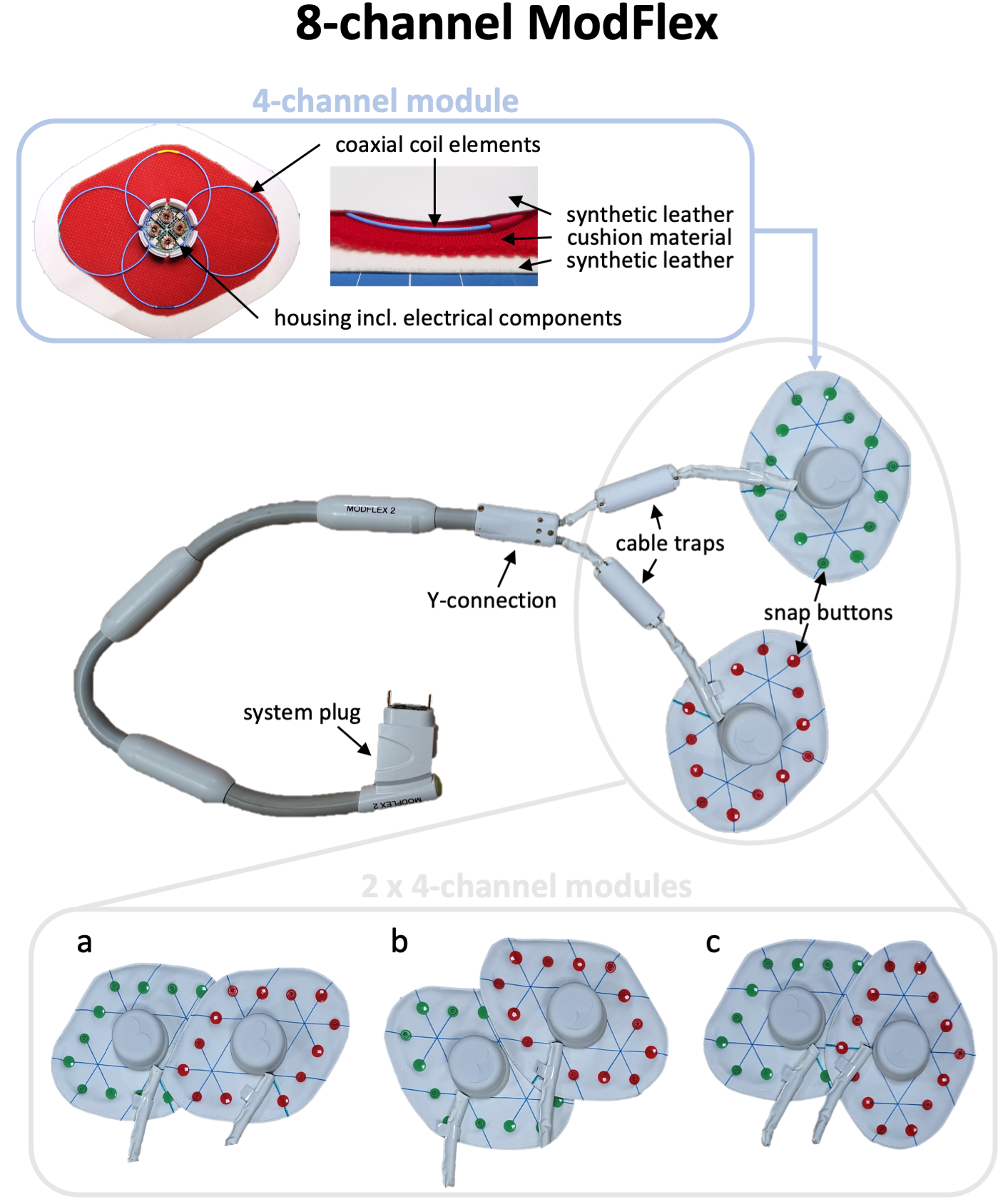
Fig. 1: Photograph of an 8-channel ModFlex coil array with details on the components of an individual 4-channel module. Each 8-channel ModFlex coil is connected to the MR system plug via a Y-connection of two 4-channel modules with a custom 3D-printed housing. Possible 8-channel array configurations are shown in a-c. Continuous lines on the upper synthetic leather layer indicate correct module assembly, i.e., ensuring overlap decoupling and mechanical stability (always two adjacent snap buttons attached).