0189
Transmission Line Receiver Coils (TLCs) for MRI
Julian Adolfo Maravilla1, Karthik Gopalan1, Ana Claudia Arias1, and Michael Lustig1
1EECS, University of California, Berkeley, Berkeley, CA, United States
1EECS, University of California, Berkeley, Berkeley, CA, United States
Synopsis
Recent advancements in MRI coil design have been made towards designing and efficiently manufacturing tailor-made MRI receive arrays utilizing a multitude of different manufacturing techniques. However, the coils in these arrays must be decoupled geometrically to prevent detuning of the individual channels. This work evaluates Twisted Pair and Microstrip based receiver coils and compares their performance to Coaxial and traditional coils in terms of SNR and decoupling.
Introduction
Multi-coil receive arrays paved the way for improved diagnostic image quality by optimally combining individual coil signals to produce images with higher SNR 1. Recent advancements have been made towards designing and efficiently manufacturing tailor-made MRI receive arrays. We have previously demonstrated body conformal, custom made receive arrays using novel fabrication methods such as screen printing, spray coating, and electroless copper 2-4. In addition to close fit to the body, coils in receive arrays must be decoupled geometrically to prevent detuning of the individual channels. Geometric decoupling is achieved by overlapping neighboring coils to reduce mutual inductance. Having to overlap traces on body conformal coils adds another layer of complexity to its manufacturing process as additional processing steps are required to electrically connect the overlapping coils. This is especially difficult on complex curvilinear surfaces4.Coaxial receive coils have been demonstrated with excellent decoupling performance without geometric decoupling5,6. As a result, receive arrays built from Coaxial coils do not need overlapping traces to achieve adequate SNR5. In this work, we compare the decoupling performance of multiple transmission line topologies (Coaxial, Twisted Pair, and Microstrip) to design new 3T coil arrays. The results from this study offer novel designs for receiver coils and paves the way for future development in the area of Transmission Line Receiver Coils.
Methods
Transmission lines are specialized structures designed to transmit electromagnetic waves in a confined manner. Fields generated by transmission lines are usually enclosed, with some topologies resulting in better shielding than others. Figure 1 demonstrates how to use transmission lines as resonant coil loops. The gap on the signal conductor acts as a feed-point for the coil, while the gap on the return conductor allows for induced current to couple onto the transmission line. An equivalent circuit model is provided in Figure 2D.Each of the three proposed transmission line topologies were fabricated with a fixed diameter of 67.5 mm. A flexible non-magnetic RG-316 cable was used for the Coaxial coils, a 28-gauge wire with Polytetrafluoroethylene (PTFE) insulation was used to form the Twisted Pairs, and Rogers RO4003C substrate was used for the Microstrip coils as shown in Figures 2A-C. The traditional coils, used as control, were fabricated on a polycarbonate substrate with copper tape as traces.
The coils were tuned and matched to 127.7 MHz with a return loss of at least 15 dB. $$$Q_{unloaded}$$$ and $$$Q_{loaded}$$$ were measured using the benchtop setup depicted in Figure 3A. Additionally, their performance was evaluated individually by measuring SNR along an image slice perpendicular to the coil. An additional decoupling experiment was performed by overlapping a pair of coils across various distances on a loading phantom and measuring insertion loss using a network analyzer (Keysight N9923A FieldFox).
Results and Discussion
To achieve body noise dominance the $$$Q_{unloaded}$$$ to $$$Q_{loaded}$$$ should be greater than two7. The Coaxial, Microstrip, and traditional coils all achieve body noise dominance. However, the Twisted Pair coils have a $$$Q_{unloaded}$$$ to $$$Q_{loaded}$$$ ratio of ~1.88. This low value is likely caused by the conductive losses associated with the 28 gauge wire used8. Thicker wire gauge could improve the $$$Q_{unloaded}$$$ performance.Following the results from the $$$Q_{unloaded}$$$ to $$$Q_{loaded}$$$ ratio experiment, Figure 4 shows the individual performance of each coil in terms of SNR. The coils that achieve body noise dominance have similar SNR performance within the phantom. However, the Twisted Pair coil has lower SNR on the surface of the phantom. This is related to the low $$$Q_{unloaded}$$$ to $$$Q_{loaded}$$$ ratio reported by the Twisted Pair coil.
The benchtop decoupling experiment reveals adequate decoupling performance for the Coaxial and Microstrip coils. Twisted Pair and traditional coils couple heavily when the overlap is set to 0 mm. As a result, the Twisted Pair coils might benefit from geometric decoupling. At an overlap of around 20 mm, the Twisted Pair and traditional coils achieve a local minimum in decoupling performance. As reported by Roemer, geometric decoupling occurs when d (Figure 5A) is around a quarter of the coil’s diameter. For a coil diameter of 67.5 mm, geometric decoupling occurs when d is 16.875 mm. Therefore, it’s expected that coils who benefit from the geometric decoupling method described by Roemer reach a minimum in $$$S_{21}$$$ at 20 mm of overlap. From the coil topologies selected for this study, the Twisted Pair coil has the least amount of shielding. As a result, more coupling is expected between Twisted Pair elements and geometric decoupling could optimize its performance.
Conclusion
Transmission Line Receiver Coils have the potential to have better innate decoupling performance when compared to traditional coils. The results from this study show that some Transmission Line topologies offer similar single coil SNR performance to traditional coils with improved decoupling performance. Future work involves investigating other Transmission Line topologies such as Strip-Line and the Coplanar Waveguide. Additionally, the performance of these coils will be examined in multi-coil arrays.Acknowledgements
This material is based upon work supported by the National Science Foundation Graduate Research Fellowship under Grant No. (DGE 1752814). Any opinions, findings, and conclusions or recommendations expressed in this material are those of the author(s) and do not necessarily reflect the views of the National Science Foundation. Additionally, the research was partially funded by NIH 1U01EB029427-01 and NIH 1U01EB025162-01.References
- Roemer, Peter B., et al. "The NMR phased array." Magnetic resonance in medicine 16.2 (1990): 192-225.
- Corea, Joseph R., et al. "Screen-printed flexible MRI receive coils." Nature communications 7.1 (2016): 1-7.
- Zamarayeva, A. M., et al. "Custom, spray coated receive coils for magnetic resonance imaging." Scientific Reports 11.1 (2021): 1-9.
- Gopalan, Karthik, et al. "Vacuum Formed Coils for Magnetic Resonance Imaging." 2021 International Conference on Electromagnetics in Advanced Applications (ICEAA). IEEE, 2021.
- Zhang, Bei, Daniel K. Sodickson, and Martijn A. Cloos. "A high-impedance detector-array glove for magnetic resonance imaging of the hand." Nature biomedical engineering 2.8 (2018): 570-577.
- Ruytenberg, Thomas, Andrew Webb, and Irena Zivkovic. "Shielded‐coaxial‐cable coils as receive and transceive array elements for 7T human MRI." Magnetic resonance in medicine 83.3 (2020): 1135-1146.
- de Beer, R. In-Vivo Magnetic Resonance Spectroscopy I: Probeheads and Radiofrequency Pulses Spectrum Analysis. Ed. M. Rudin. Springer Berlin Heidelberg, 1992.
- Pozar, David M. Microwave engineering. John wiley & sons, 2011.
Figures
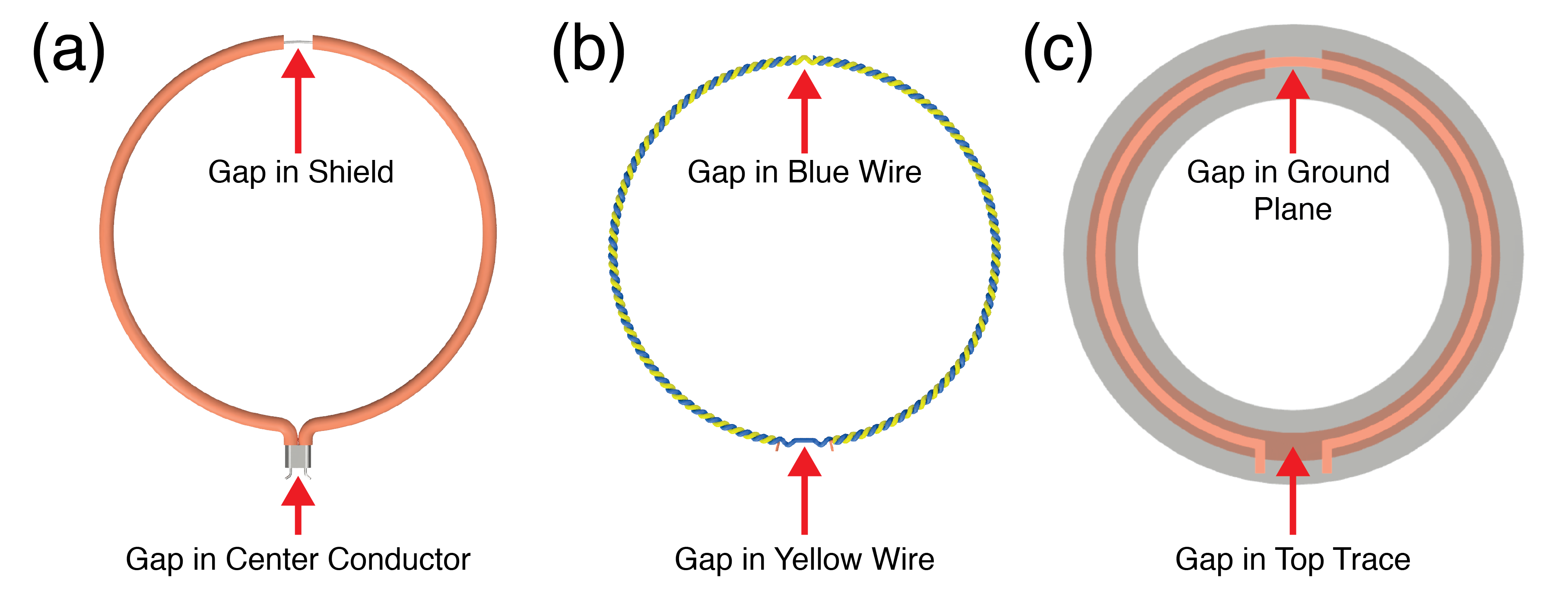
Figure 1: Transmission Line Resonant Coil Loops: (a) Coaxial Loop, (b) Twisted Pair Loop, and (c) Microstrip Loop. The red arrows indicate where the gaps lie on the individual topologies.
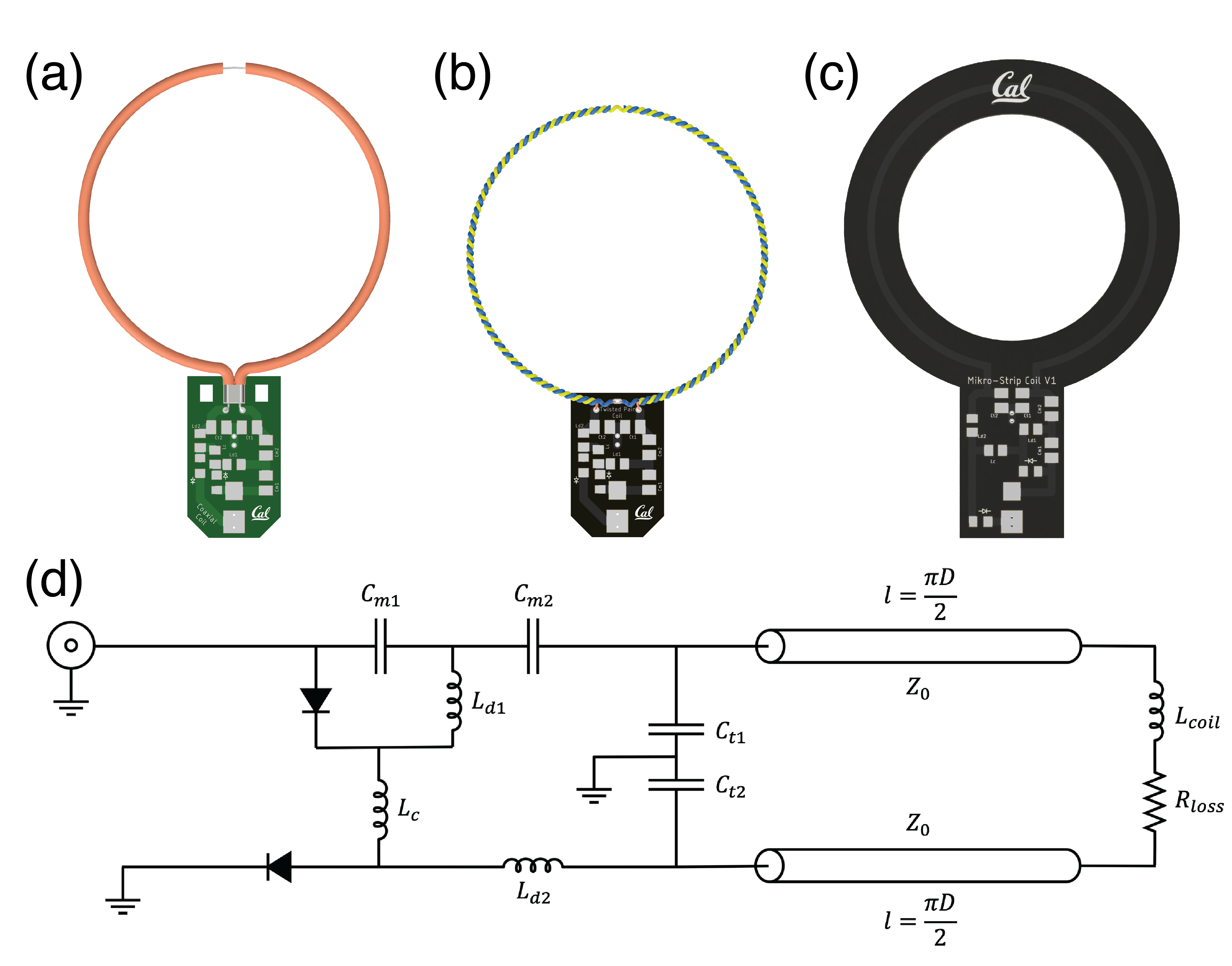
Figure 2: Topology of Transmission Line Receiver Coils: (a) Coaxial Receiver Coil, (b) Twisted Pair Receiver Coil, (c) Microstrip Receiver Coil. (d) Equivalent distributed model for TLCs. The signal induced on the coil is modeled by $$$L_{coil}$$$ whose value is dependent on the Transmission Line topology and the diameter of the coil. $$$R_{loss}$$$ models the losses in the coil, and from the body. Different $$$Q$$$-Spoiling topologies can be used to detune and block current on the coil during the transmit phase of a scan.
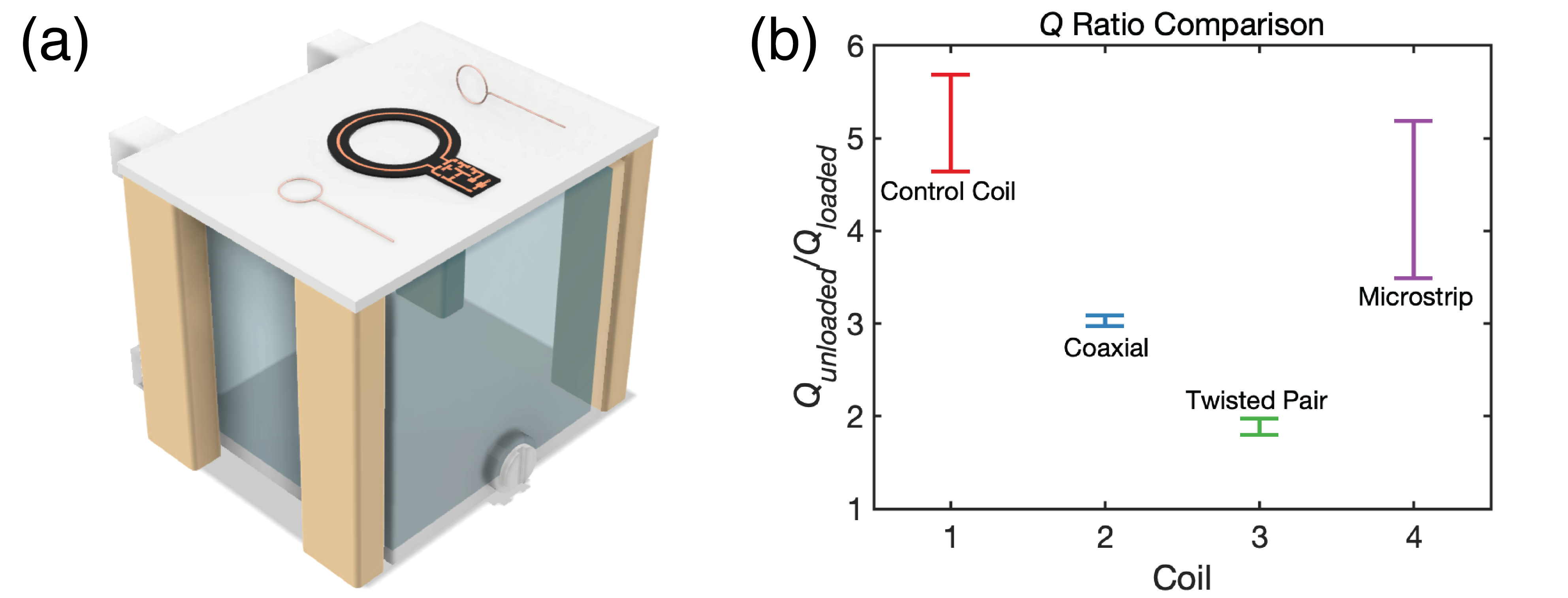
Figure 3: Coil $$$Q$$$ Measurements. (a) Test bench setup for $$$Q$$$ characterization: a small table on top of a removable loading phantom, and two broadband sniffer probes used to excite the coils. (b) $$$Q_{unloaded}/Q_{loaded}$$$ ratio measured for each coil. Multiple coils were measured to ensure repeatability. The error bars represent 3 standard deviations.
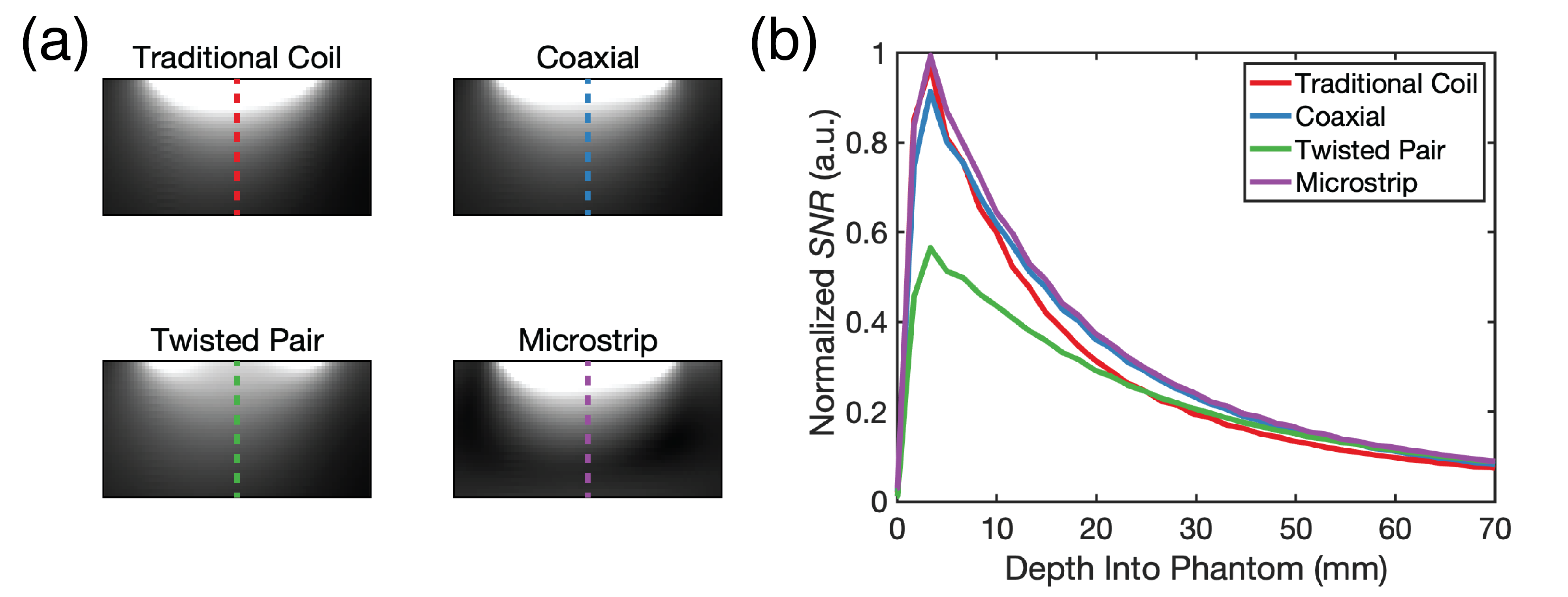
Figure 4: Single Coil SNR Comparison. (a) Sensitivity Maps. Each coil was placed on a rectangular loading phantom. An image slice was taken perpendicular to the center of the coil. Image voxels along the dashed line were used to compute SNR. (b) Normalized SNR plot for each coil.
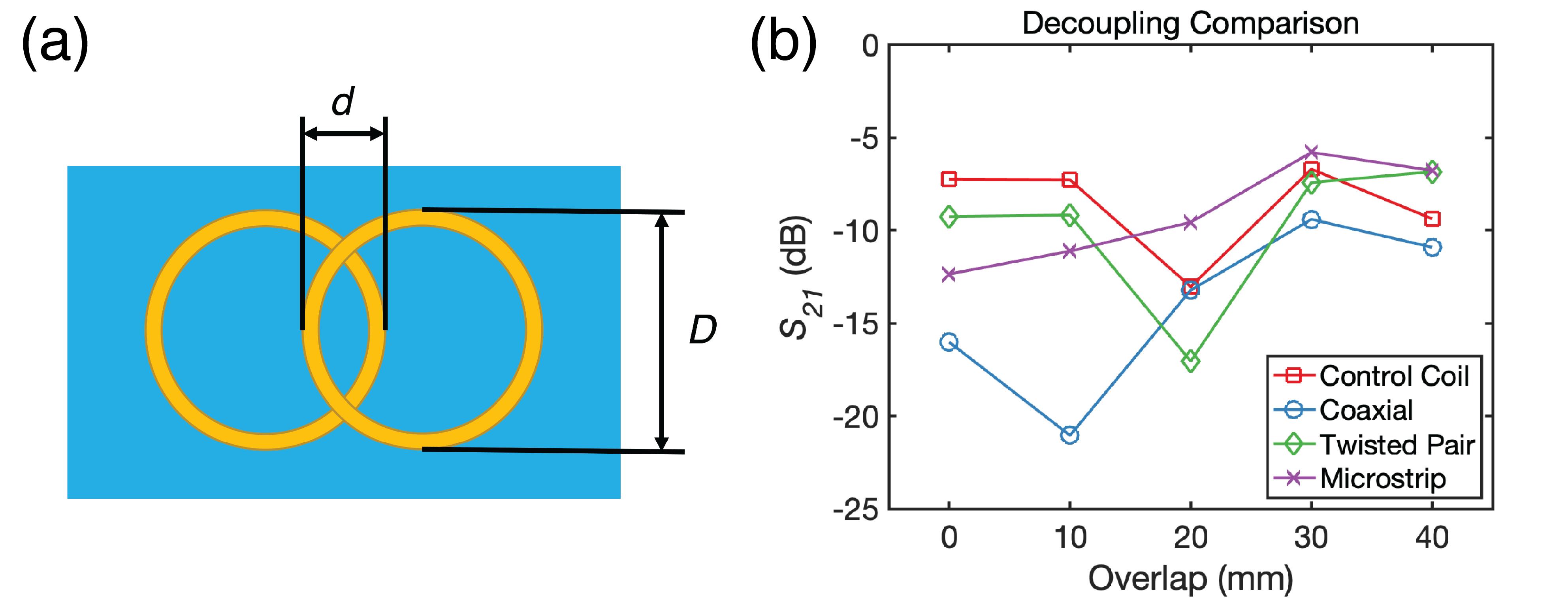
Figure 5: A stationary coil is placed on a rectangular loading phantom. (a) The overlap distance d is varied from no overlap to 40 mm overlap in increments of 10 mm. The diameter of the coil, D, is 67.5 mm. (b) $$$S_{21}$$$ obtained for each pair of coils at different overlapping conditions.
DOI: https://doi.org/10.58530/2022/0189