0186
Light Coils: MRI with Modular RF Coils UsingOptical Power and Data Transmission
1Dept. Radiology, Medical Physics, Medical Center - University of Freiburg, Freiburg, Germany, 2Gisela and Erwin Sick Laboratory for Micro-Optics, Department of Microsystems Engineering, University of Freiburg, Freiburg, Germany
Synopsis
An optically powered and broadcasted modular receive coil concept (Light Coils) is presented for MRI to simultaneously eliminate the challenges in MRI of pediatric or overweight patients, signal-to-noise ratio losses and potential safety hazards due to electro-magnetic interferences in the transmission cables, and Ohmic losses in the metallic wires. By combining innovative RF antenna architectures, low-noise-low-power front end electronics and state-of-the-art silicon photonics technology, Light Coils might offer a robust and scalable solution for MRI image acquisition. Preliminary experimental results on the power-on-fiber driving of LNAs, and optical active detuning of receive coils are also discussed.
Introduction
Designing a coil array that closely fits the region of interest is readily achievable[1]–[8], but to use the same coil in patients with varying size and body shape can be challenging as it requires the coil array to be shape/form adaptive. Electrically conducting cables in general present a potential safety hazard due to potential RF coupling during excitation. Furthermore, densely packed cables in Rx arrays can reduce the SNR due to cable cross-talk. They also increase the total weight of the RF coil and complicate the patient preparation for an MRI exam. To overcome this problem optical data transmission systems have been proposed [9]–[15]. However, galvanic connections are still needed to supply and drive the electronics. Power-over-fiber (PoF) is a promising alternative to the galvanic connections. We propose a novel modular MRI receive coil concept (Light Coils) which uses optical power and data transmission. This concept envisions light-weight, flexible and connectable coil elements to enable the generation of various coil shapes (Fig. 1) to increase the image quality.Methods
The Light Coil concept consist of coil elements that are combined via optical fiber connectors which connect each element to a power and a signal backbone (Fig.2A). Each Light Coil element is associated with a specific light color (i.e., wavelength l) for power and signal transmission over the backbone fibers. For power delivery (Fig. 2A) the light of N light sources (e.g., high-power lasers each with ~100 mW optical power) with N different wavelengths are coupled into the single power backbone fiber through a high-power DWDM multiplexer. At each Light Coil element an optical circulator with a distributed Fiber Bragg (DFB) grating extracts a specific wavelength li from the incoming spectrum onto a photodetector cell for opto-electronic energy conversion (Fig.2B). This energy is then used to power a pre-amplifier circuitry during MR signal reception (Fig.2C). The analog MR receive signal is then transmitted optically over the parallel signal backbone via a data encoding unit comprising a Photonic Integrated Chip (PIC) and a laser micromachined glass integration platform to facilitate optical interfacing.Similar to the power backbone described earlier, the signal backbone relies on the dense wavelength division multiplexing (DWDM) principle. Optical MR signal transmission has been demonstrated in previous works [9]–[15] both in digital and analog domain. The data backbone of the Light Coil concept differs from the previous work in two important aspects: 1) through wavelength multiplexing, Information from all the coils are transmitted over a single fiber, which simplifies the clinical imaging work flow; 2) individual coils encode the MR data by modulating a continuous wave light delivered from the multiplexer, rather than having separate light sources on the coil elements, which reduces power consumption and the complexity of the on-coil electronics.? Similar to the power backbone described earlier, the signal backbone relies on the DWDM principle. Since the optical MR signal transmission has been demonstrated in previous works[9]–[15] both in digital and analog domain, we will focus on demonstrating the feasibility of power over fiber for RF coils in this study.
To use the Light Coil technology even in dense coil arrays with up to 128 channels, the power requirements for each element need to be minimized. Here, we propose optical active detuning, and a low-power low-noise amplifier design. For optical detuning, PhotoFETs can be optically switched without the need for optical-to-electrical power conversion to bias a PIN diode (Fig. 3A,B). In Fig.3C, the setup to demonstrate the feasibility of optical active detuning is shown. To improve coupling efficiency and thus to reduce the optical power requirements, a glass fiber coupler was manufactured using selective laser-induced etching (SLE[16])(Fig.3D).
To further reduce power requirements, a low-power LNA was designed which requires only 20 mW (Fig.4A,). This design was implemented on a 2-layer 12x25mm2 PCB (Fig.4B) and feasibility of optical powering was tested. MRI measurements using a prototype Light Coil element was performed in a phantom and a volunteer measurement.
Results
In Fig. 3E,F, MR images of using optical and conventional detuning are shown for 220mW optical power. A minimum of 17mW optical power was needed for sufficient detuning. In Fig.3G,H, optical detuning performs comparable as the conventional detuning as indicated by the SNR values. In Fig.3I, an image acquired with the body coil when there is no active detuning is shown. Sensitivity is inhomogeneous and the SNR is reduced. Optical detuning provides sufficient decoupling during Tx cycle (Fig.3J).The LNA required 5V at 4.6mA for 22.5dB gain but yielded higher noise figure compared to the simulations (Fig. 4E,F). The PoF setup provided 3.1V at 21mA converting the 1.7W laser power to electrical power via a free-space laser to fiber coupling system which can be improved using fiber-coupled lasers and direct coupling to the photo diode. Preamplifier decoupling performance of the low-power LNAs were comparable to the commercial LNAs (17±2dB vs. 19±4dB). Image SNR of the same coil setup for commercial and low-power LNA was 1075±122 and 886±93, respectively within the selected ROI.
In Fig. 5, transverse slices from the MR images acquired using optical power and detuning with conventional signal transmission are shown.
Discussion
We discussed feasibility of power-over-fiber techniques to replace conventional power network in RF coils, which is a key factor for enabling Light Coil technology. Reducing the power requirements is key for dense Light Coil arrays. The image SNR with the low-power LNAs was lower, which can be attributed to lower voltage bias at the photodiode output during the experiments. We aim for higher optical transmission efficiency in future prototypes using dedicated components with fiber coupling.Acknowledgements
No acknowledgement found.References
[1] H. J. Zabel, R. Bader, J. Gehrig, and W. J. Lorenz, “High-quality MR imaging with flexible transmission line resonators.,” Radiology, vol. 165, no. 3, pp. 857–859, Dec. 1987, doi: 10.1148/radiology.165.3.3685365.
[2] R. Kriegl et al., “Novel inductive decoupling technique for flexible transceiver arrays of monolithic transmission line resonators,” Magn. Reson. Med., vol. 73, no. 4, pp. 1669–1681, Apr. 2015, doi: 10.1002/mrm.25260.
[3] J. R. Corea et al., “Screen-printed flexible MRI receive coils,” Nat. Commun., vol. 7, p. 10839, Mar. 2016, doi: 10.1038/ncomms10839.
[4] B. Zhang, D. K. Sodickson, and M. A. Cloos, “A high-impedance detector-array glove for magnetic resonance imaging of the hand,” Nat. Biomed. Eng., pp. 1–8, May 2018, doi: 10.1038/s41551-018-0233-y.
[5] K. P. McGee et al., “Characterization and evaluation of a flexible MRI receive coil array for radiation therapy MR treatment planning using highly decoupled RF circuits,” Phys. Med. Biol., vol. 63, no. 8, p. 08NT02, Apr. 2018, doi: 10.1088/1361-6560/aab691.
[6] R. Frass-Kriegl et al., “Multi-turn multi-gap transmission line resonators – Concept, design and first implementation at 4.7 T and 7 T,” J. Magn. Reson., vol. 273, pp. 65–72, 2016, doi: 10.1016/j.jmr.2016.10.008.
[7] A. C. Özen et al., “Design of an Intraoral Dipole Antenna for Dental Applications,” IEEE Trans. Biomed. Eng., vol. 1, no. 1, pp. 1–1, 2021, doi: 10.1109/TBME.2021.3055777.
[8] T. Ruytenberg, A. Webb, and I. Zivkovic, “Shielded‐coaxial‐cable coils as receive and transceive array elements for 7T human MRI,” Magn. Reson. Med., vol. 83, no. 3, pp. 1135–1146, Mar. 2020, doi: 10.1002/mrm.27964.
[9] D. Gupta, O. Mukhanov, and R. E. Hitt, “DIGITAL RADIO FREQUENCY TRANCEIVER SYSTEMAND METHOD,” US 8,260,144 B2, 2012.
[10] O. G. Memis, Y. Eryaman, O. Aytur, and E. Atalar, “Miniaturized fiber-optic transmission system for MRI signals,” Magn. Reson. Med., vol. 59, no. 1, pp. 165–173, 2008, doi: 10.1002/mrm.21462.
[11] S. Fandrey, S. Weiss, and J. Müller, “A novel active MR probe using a miniaturized optical link for a 1.5-T MRI scanner,” Magn. Reson. Med., vol. 67, no. 1, pp. 148–155, Jan. 2012, doi: 10.1002/mrm.23002.
[12] W. Tang et al., “A home-built digital optical MRI console using high-speed serial links,” Magn. Reson. Med., vol. 74, no. 2, pp. 578–588, Aug. 2015, doi: 10.1002/mrm.25403.
[13] A. Simonsen, J. D. Sánchez-Heredia, S. A. Saarinen, J. H. Ardenkjær-Larsen, A. Schliesser, and E. S. Polzik, “Magnetic resonance imaging with optical preamplification and detection,” Sci. Rep., vol. 9, no. 1, p. 18173, Dec. 2019, doi: 10.1038/s41598-019-54200-3.
[14] H. H. Tuithof, J. H. Den Boef, and V. J. E. W, “Magnetic Resonance Examination Apparatus and Method of Performing an Examination Using Magnetic Resonance,” WO 2004/089211 A2, 2004.
[15] R. M. Hoogeveen, “MR COIL WITH FIBER OPTICAL CONNECTION,” US 8,324,899 B2, 2012.
[16] M. Hermans, “Selective, Laser-Induced Etching of Fused Silica at High Scan-Speeds Using KOH,” J. Laser Micro/Nanoengineering, vol. 9, no. 2, pp. 126–131, Jun. 2014, doi: 10.2961/jlmn.2014.02.0009.
Figures
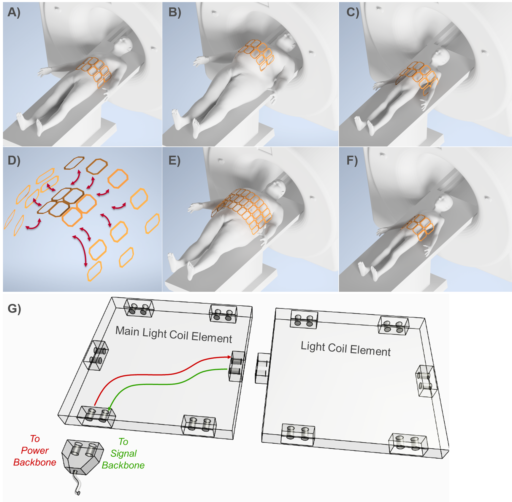
Fig.1: Illustration of the need for a modular coil array on human body models with various size. Standard body coil array placed on a model with a BMI of A) 28 and B) 34. The coil does not fit. C) Child body. Large gaps cause SNR degradation. D) Modular coil concept to form larger or smaller coil arrays to fit a broad range of patients such as E) BMI of 34 and F) children to increase SNR and reduce scan times. G) An example of a potential implementation scenario for Light Coils. Two Light Coil elements are connected via optical connectors. Each connector has two channel: one for power, one for MR signal.

Fig.2: A) Power and signal backbones of the Light Coils concept. There are no metallic cables for MR signal and power transmission. Signal from Light Coil elements is combined optically, and transmitted over an optical transmission line to the signal backbone, where the signal is demultiplexed and sent to digital receivers. B) Schematic of the signal chain and power supply in a Light Coil element. C) A potential implementation of power over fiber for optical detuning and powering. Coil elements share the active detuning signal, yet each coil is powered by light at a specific wavelength.
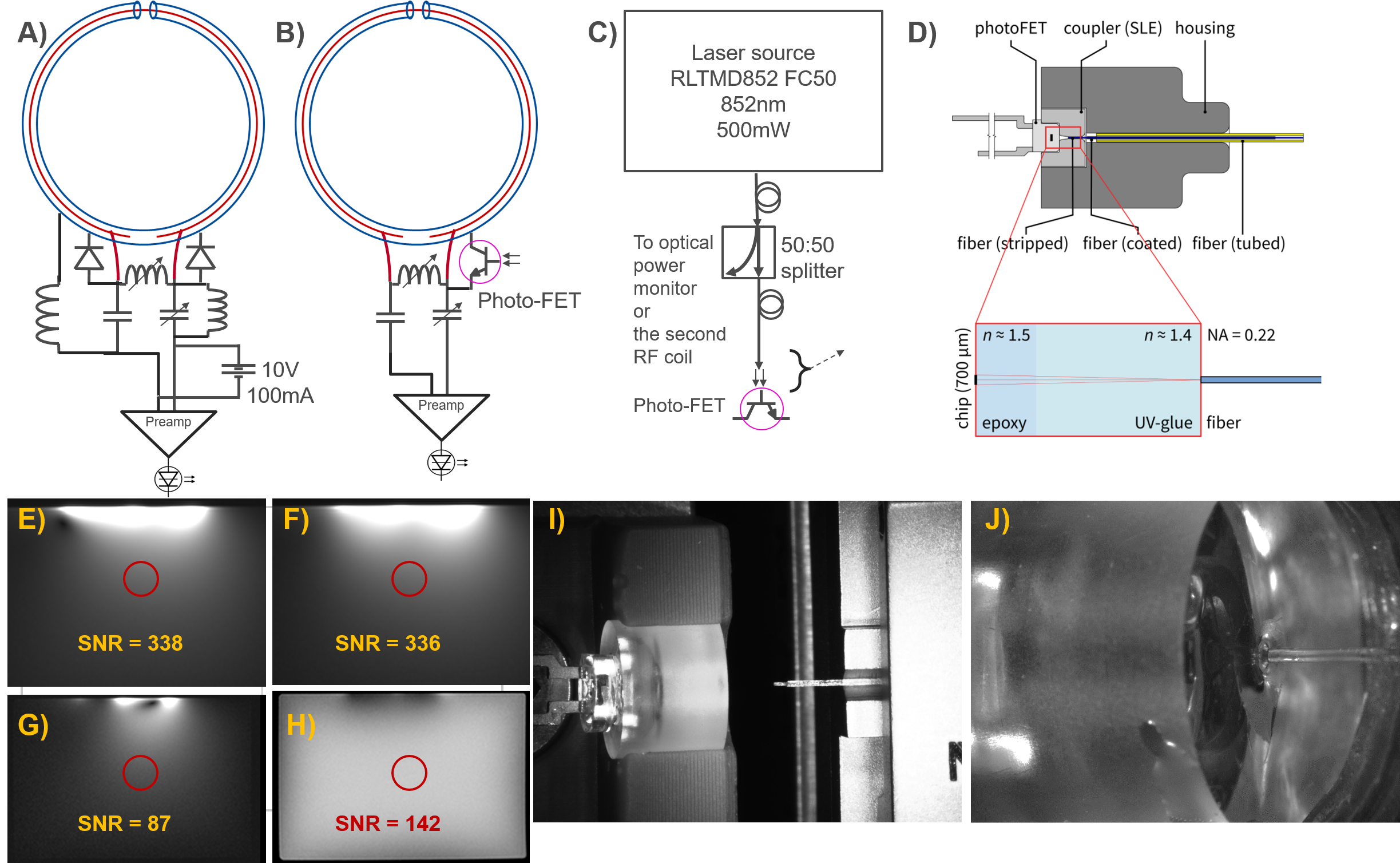
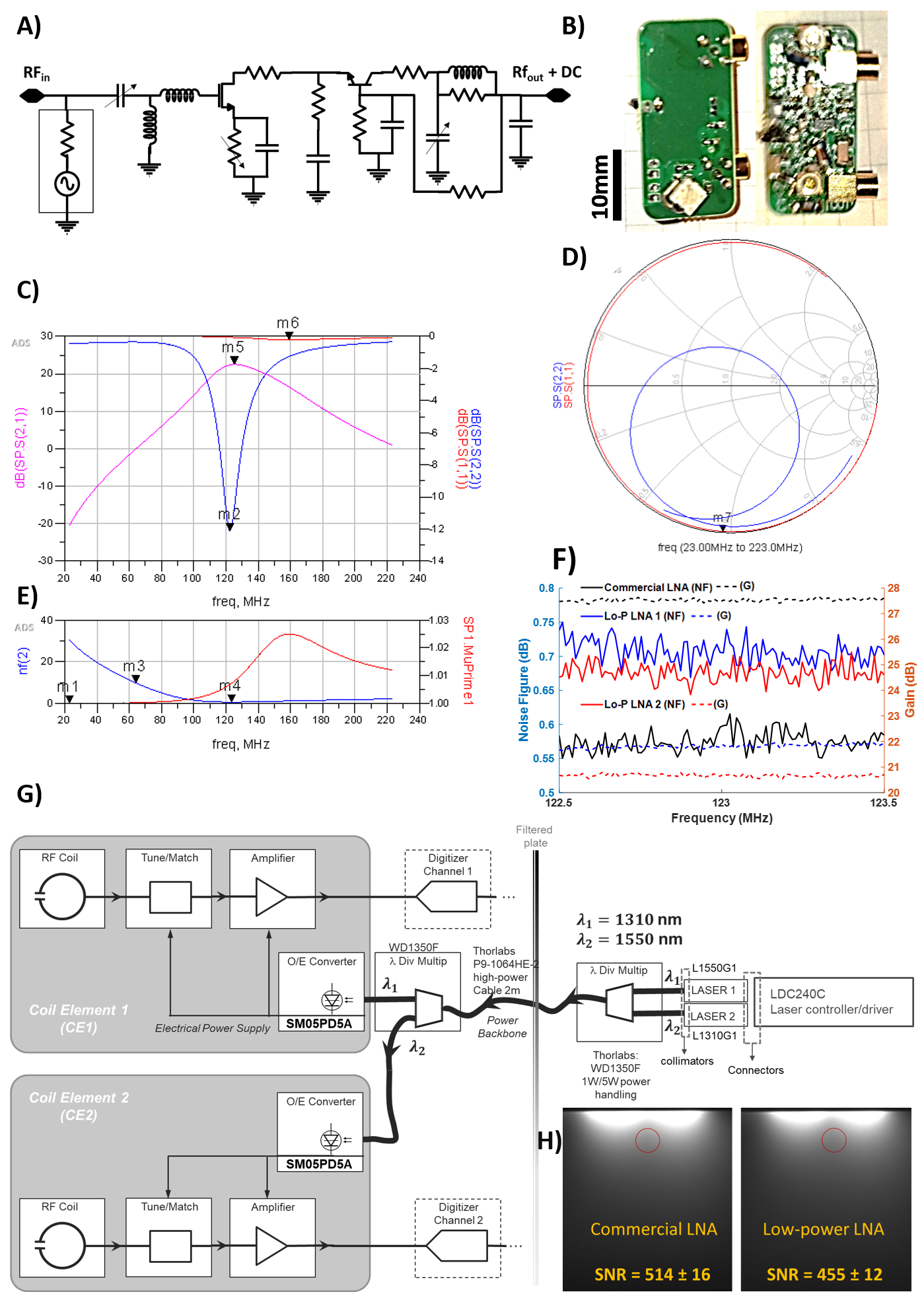
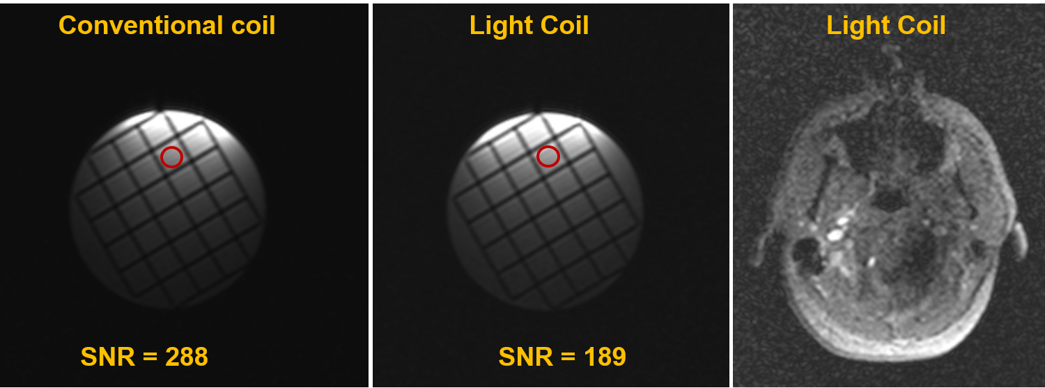
Fig.5: MR images of a resolution phantom acquired using a conventional coil element (A) and an optically powered and detuned Light Coil element (B). A transverse slice from the head of a healthy volunteer using a single-channel Light Coil prototype with optical power transmission and optical detuning acquired with a 1.1s-long 2D GRE sequence (C).