0064
Low-cost Modular RFPA Platform for Gradient-Free Quantitative Imaging1Physics, Case Western Reserve University, Cleveland, OH, United States, 2Biomedical Engineering, Vanderbilt University, Nashville, TN, United States, 3Radiology, Case Western Reserve University, Cleveland, OH, United States
Synopsis
This work presents a $75 phase modulated 2.07MHz radiofrequency power amplifier (RFPA) measuring 8.5x4.5cm for Selective Encoding through Nutation and Fingerprinting (SENF). By eliminating the need for a gradient system and imaging in a low B0, SENF shows great potential to reduce the cost, size, and accessibility of magnetic resonance imaging (MRI) equipment. Here we present the development of a transmit stage of a SENF coil unit. Special consideration has been given to simplifications that can be made in RFPA design in this specific application.
Instroduction
A new magnetic resonance encoding method was recently proposed, Selective Encoding through Nutation and Fingerprinting (SENF) [1], based on parallel transmission[2] of B1+-selective pulses[3], and magnetic resonance fingerprinting[4] inspired acquisition and reconstruction. This method eliminates conventional B0 gradients and the need for strictly controlled radiofrequency gradient variation. By eliminating the need for a gradient system and imaging in a low B0, SENF shows great potential to reduce the cost, size, and accessibility of MRI systems. Here we present the development of a transmit stage of a SENF coil unit. Special consideration has been given to simplifications that can be made in radiofrequency power amplifier (RFPA) design in this specific application.Methods
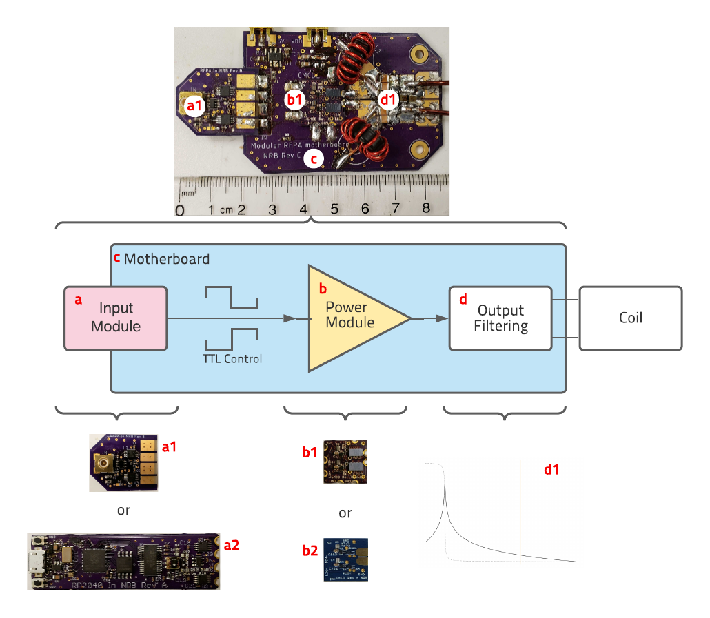
DesignThe goal of prototype the SENF RFPA design was to be as small, inexpensive, and simple as possible for a B0 of 47 mT corresponding to 2.07MHz. SENF transmit pulses require only phase modulation at a maximum 100kHz bandwidth at a constant amplitude. With that in mind, the design started by pairing down previous compact current mode class D (CMCD) eGaN FET RFPA designs [5]. Additionally, this design was made to be modular, consisting of power modules and input modules which mount on a motherboard with space for output filters (see figure 1). This made the RFPA easier to repair and adapt, and sacrificed little space.
The core of the amplifier was the GaN-based switch-mode power amplifier module measuring 15mm by 15mm. This was driven by TTL to control switching, and was designed for several models of GaN FETs, overa a of power handling and switching characteristics. In this application, trading low input and output capacitance for high power was acceptable, given the low frequency. This led to the choice of the EPC2034c, rated for 200V drain to source voltage, and 48A continuous drain current without any exterior thermal management.
For design of the output stage of the amp, SPICE simulations of active components were available from the vendors, and parasitic properties of PCB geometry were negligible, so simple simulations often yielded helpful results. The choice was made to construct the simplest design possible with DC-blocking capacitors at the drain and using the coil itself as a frequency filter. Multiple prototypes of the small signal stage of the amp were developed for different external driving schemes and for on-board pulse generation. These “input modules” produce TTL to drive the power switching module. Early testing was done with a simple translator module (a1 in Figure 1) which converts external low-amplitude phase-modulated inputs to 50% duty cycle TTL pulses.
Fabrication
While parts and materials for this design were inexpensive, fabricating the power stage required mounting small (0.8x1.2mm) ball grid array (BGA) components, which may be challenging or expensive. The easiest way to fabricate the modular RFPA for SENF v1 was to order parts and PCBs, and reflow solder the small components. This can be done with a well controlled toaster oven, but the modular design also allows for much adaptation and repair with only hand soldering by having the power modules prefabricated. Contracting Bittele, a PCB assembly service, to fabricate power modules cost approximately $20 more per module for the EPC2012c module (b2 in Figure 1). For prototyping new power modules, in-lab assembly was required, but otherwise they may be bulk prefabricated.
Testing
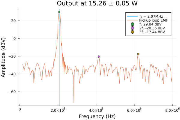
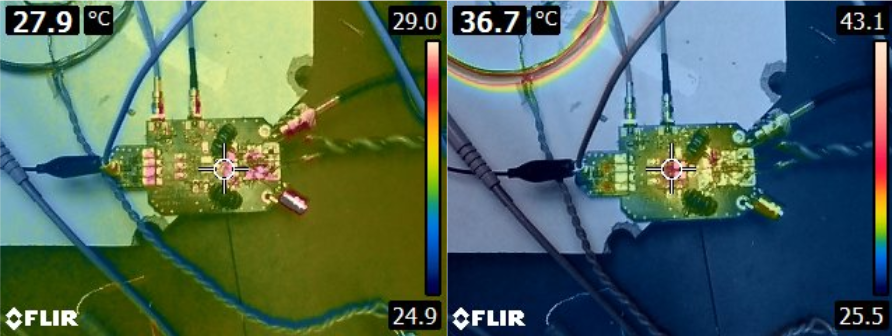
The modular RFPA for SENF v1 was tested for efficiency and pulse accuracy. The coils used for analysing output were a 10 turn, 10cm coil, with a 5 turn, 5cm coil for pickup. For efficiency, voltage across a 39Ω resistive load was measured with an Agilent DSO7054B oscilloscope, and the amplifier was driven by a Rigol DG4162 arbitrary waveform generator into the translator module (a1 in Figure 1). For preliminary SENF experiments, a 36 turn, 12cm radius, 20cm length solenoid was used, and the amp was again driven externally by a low voltage signal into the translator module (a1 in Figure 1).
Results
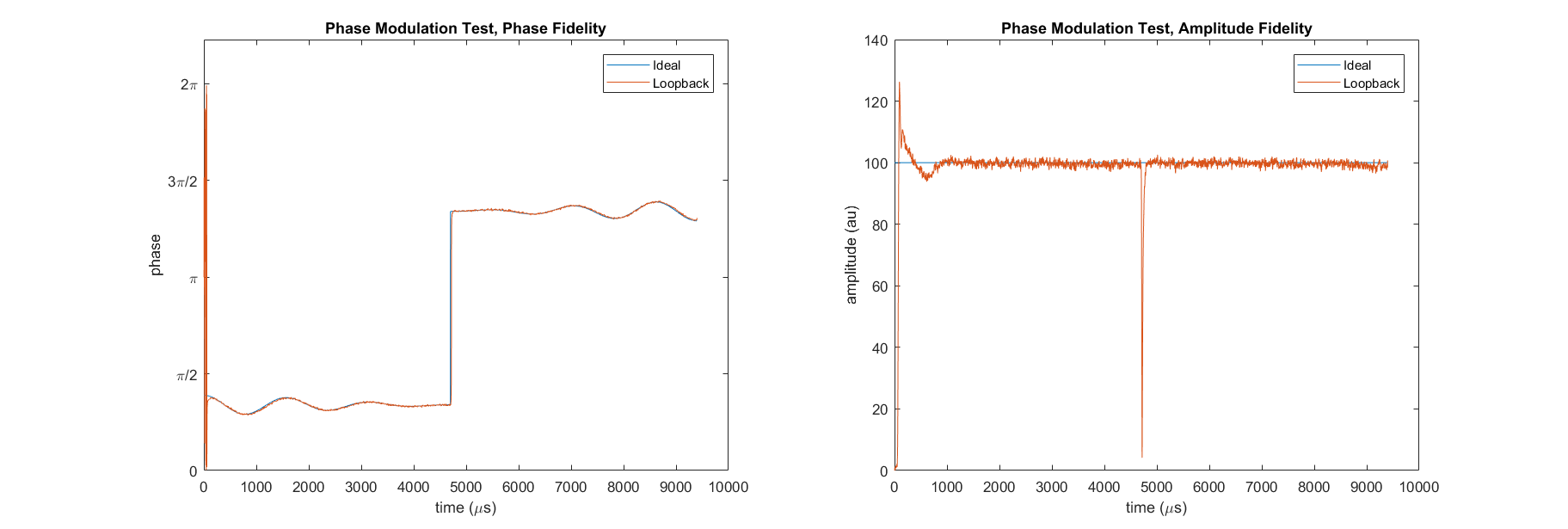
See figures 2 and 3 for the results of continuous output tests at 15W. See figure 4 for results of a test pulse at 12W.Cost
Total conservative cost estimate for components and PCBs to build an EPC2034c power module is $30 ($26.75 each for a batch of 20). A conservative estimate of motherboard cost is $24. The input module is $22, and the RP2040 based pulse generating input module is $46. The total cost for this version of the modular SENF RFPA is $76, and the wirelessly controlled version is $100.
Conclusions
It is possible to build a highly compact amplifier for SENF MRI for under $75. Because of the simplicity of the requirements, this simplified design should be adaptable to other frequencies for SENF imaging at other low field strengths. This design is the first part of a similarly minimalist on-coil wirelessly-controlled transmit and receive device for SENF MRI. Next steps will be designing modules to add the receive stage of the SENF coil unit.Acknowledgements
No acknowledgement found.References
[1] C E Vaughn, M A Griswold, and W A Grissom. MR Barcoding: Gradient-Free MRI Using B1-Selective Parallel Transmission. Proceedings 28th Meeting of the International Society for Magnetic Resonance in Medicine, Virtual, 2020, p. 620.
[2] N. Gudino, J. A. Heilman, M. J. Riffe, O. Heid, M. Vester, and M. A. Griswold, “On-coil multiple channel transmit system based on class-D amplification and pre-amplification with current amplitude feedback: On-Coil Current-Mode Parallel Transmit System,” Magn. Reson. Med., vol. 70, no. 1, pp. 276–289, Jul. 2013, doi: 10.1002/mrm.24462.
[3] W. A. Grissom, Z. Cao, and M. D. Does, “|B1+|-selective excitation pulse design using the Shinnar–Le Roux algorithm,” J. Magn. Reson., vol. 242, pp. 189–196, May 2014, doi: 10.1016/j.jmr.2014.02.012.
[4] D. Ma et al., “Magnetic resonance fingerprinting,” Nature, vol. 495, no. 7440, pp. 187–192, Mar. 2013, doi: 10.1038/nature11971.
[5] M. Twieg and M. A. Griswold, “High efficiency radiofrequency power amplifier module for parallel transmit arrays at 3 Tesla: High Efficiency in-Bore RFPA Module for pTX at 3T,” Magn. Reson. Med., vol. 78, no. 4, pp. 1589–1598, Oct. 2017, doi: 10.1002/mrm.26510.
Figures