0062
EMI-Suppressed Gradient-Free Phase-Encoded Imaging at 47.5mT Using an Optimized Square-Root Solenoid for Encoding and a Saddle Coil for Imaging
Sai Abitha Srinivas1,2, Christopher E Vaughn1,2, Jonathan B Martin1,2, and William A Grissom1,2,3,4
1Biomedical Engineering, Vanderbilt University, Nashville, TN, United States, 2Vanderbilt University Institute of imaging science, Nashville, TN, United States, 3Radiology, Vanderbilt University, Nashville, TN, United States, 4Electrical Engineering, Vanderbilt University, Nashville, TN, United States
1Biomedical Engineering, Vanderbilt University, Nashville, TN, United States, 2Vanderbilt University Institute of imaging science, Nashville, TN, United States, 3Radiology, Vanderbilt University, Nashville, TN, United States, 4Electrical Engineering, Vanderbilt University, Nashville, TN, United States
Synopsis
Traditional B0 gradients have several drawbacks including high acoustic noise, PNS, bulkiness, and high cost. To address this, we demonstrate the use of Bloch-Siegert (BS) RF encoding for phase encoding using an optimized square root solenoid with a Bucking coil for high efficiency encoding and a nested uniform saddle coil for the imaging Tx/Rx coil at 47.5mT, a field strength that is especially attractive due to its low SAR and accessibility. The coil performance was evaluated in simulation and experimentally, and 2D BS phase encoded imaging and reconstructions were performed using optimized ‘U’ shaped BS pulses.
Introduction
In conventional MRI, signal is localized using B0 gradients that link spatial position to signal frequency, but they are expensive, loud, induce PNS, and are prone to breakage. B1+ gradients can alleviate these problems [1-8]. However, RF coils producing the appropriate B1+ gradients are challenging to build. Solenoids with square-root pitch for Bloch-Siegert (BS) encoding need to be made longer than the imaging volume to achieve the desired square-root field in the imaging ROI, which limits their efficiency. To address this, we propose an optimized square root solenoid with a Bucking coil for encoding for BS spatial encoding, with a geometrically decoupled saddle coil inside it for excitation and reception. We demonstrate a phase encoding experiment with optimized frequency swept ‘U’-shaped BS pulses for phase encoding on a 47.5mT system with three reconstruction techniques.Methods
2D phase encoded imaging was implemented on a 47.5mT scanner (Sigwa 48.7mT, Boston NMR, Boston, MA) shown in Figure 1A. The RF coils were placed in a shielded box and remaining EMI was removed using EDITER [9] with two external EMI detector coils.Figure 1B shows the two-coil setup with 1) The 2.075MHz litz-wire optimized square root coil for phase encoding, and 2) A uniform saddle coil (OD of 3D printed former = 3.5cm, length = 12cm) for imaging. Optimization of the square-root coil was done numerically by minimizing the B1+-field of a regular square-root solenoid to be close to an ideal square-root B1+-field. The winding pattern of an optimized coil is shown in Figure 1C. Figure 1D shows the isolation (-36dB) between the geometrically decoupled solenoid and saddle coils. Bucking coil windings were added to cancel fringe B1+-field at the low B1+-field edge of the solenoid coil and make the coil more efficient. This effect can be seen in Figure 2A wherein an analytic square root coil is compared to the optimized coil with and without the bucking coil windings (Total # of windings for each = 34, excluding the bucking coil). Since the frequency and phase shifts applied to an object by BS encoding are proportional to B1+2, Figure 2B shows average B1+2 profiles across the ROI along with linear fits and their R2. Figure 1C shows Experimental B1+ maps which were obtained from a 11.5cm(L) x 3cm(D) tube mineral oil phantom using the optimized ‘U’ shaped BS pulse [10] shown in Figure 3A (BS frequency-offset =20KHz and Kbs[11] =43.5). Figure 1D shows the average B1+2 profile across the tube phantom along with a linear fit and its R2.
The same optimized BS pulse was used for phase encoding in a 2D GRE sequence (Sequence parameters: TE=17ms, TR=534ms, NPE=67, NFE=128, Naverages=5) shown in Figure 3B. The BS pulse amplitude was varied for BS phase encoding (NBS=37). The uniform saddle coil was used for Tx/Rx for imaging with an active T/R switch [12]. The optimized solenoid was used for encoding. B0 gradients were used for frequency encoding along the Z direction(kx). A scanner drift navigator sequence was interleaved with the acqusition.
The Reconstruction pipeline is shown in Figure 4. Here, the full phase encoded tube dataset was taken and then scanner drift corrected. This resulting dataset was used to create an encoding matrix (E). A full model-based reconstruction(R) done using the following equation:
$$ R = {(E'E + \lambda I)}^{-1} E S$$
Where, S is the hybrid (x-ky) data for a two-ball mineral(2cm) oil phantom and $$$\lambda$$$ is the regularization parameter. Additionally, a least-squares NUFFT reconstruction was performed by calculating the slopes of the BS phase encoded lines of the tube phantom to determine the actual ky locations. A partial Fourier reconstruction was performed using 70% of the ky lines which comprised all the positive encodes and 40% of the negative encodes. MATLAB’s lsqnonlin (Mathworks,Natick,MA) was used to reconstruct the image, holding the phase image fixed to match a zero-filled recon.
Results
Linear fits of B1+2 and their R2 in Figure 2B show that the optimized square root solenoid had the highest linearity (R2=0.9987) which agreed with the R2(0.9960) of the linear fit for the experimental results in Figure 2D. Since efficiency depends on the slope of the B1+2-field the y-intercepts are shown for each fit (retaining same slopes) to show that the optimized coil with the bucking windings was 20% more efficient than the one without the bucking windings. Figures 5A-D show the results from the three types of reconstructions in comparison to a fully B0-encoded two-ball phantom image. Figure 5E shows two-ball phantom 1D profiles at the same points in all the reconstruction methods and from Figure 5F we can observe that the FWHM’s closely align with the B0-encoded image. The NUFFT reconstruction had the closest fit to the B0-encoded image.Discussion
We demonstrated a robust method to perform B1+ phase encoding using an optimized square root solenoid. Adding the Bucking coil to null the low-field, we obtained a 20% power efficiency improvement compared to the optimized design. The interleaved drift navigator scans could be eliminated by adding an FID measurement during the dead time between the excitation and BS encoding pulse. In future work, we will linearize the phase encodes to enable Cartesian FFT reconstruction.Acknowledgements
Funding source R01 EB030414. We would like to thank Siddhant Gandhi for helpful discussions about RF coil design.References
1. Hoult D. Rotating frame selective pulses, J. Magn. Reson. 38 (1980) 369–374.2. F Bloch and A Siegert. Magnetic resonance for nonrotating fields. Phys Rev, 57:522–527, 1940.
3. R Kartausch, T Driessle, T Kampf, T C Basse-Lusebrink, U C Hoelscher, P M Jakob, F Fidler, and X Helluy. Spatial phase encoding exploiting the Bloch-Siegert shift effect. Magn Reson Mater Phy, 2013.
4. C J Hasselwander and W A Grissom. Bloch-Siegert phase-encoded MRI with a single RF coil and frequency swept pulses. In Proceedings 25th Scientific Meeting, International Society for Magnetic Resonance in Medicine, Honolulu, p5047, 2017.
5. C Zimmerman Cooley. Portable Low-Cost Magnetic Resonance Imaging. PhD thesis, Massachusetts Institute of Technology, 2014.
6. Torres, E, Froelich, T, Wang, P, et al. B1-gradient–based MRI using frequency-modulated Rabi-encoded echoes. Magn Reson Med. 2021; 00: 1– 12. https://doi.org/10.1002/mrm.29002.
7. Jankiewicz M, Gore JC, Grissom WA. Improved encoding pulses for Bloch-Siegert B1(+) mapping. J Magn Reson. 2013;226:79-87. doi:10.1016/j.jmr.2012.11.004.
8. Khaligi M, Rutt B, Kerr A. Adiabatic RF Pulse Design for Bloch-Siegert B1+ Mapping. Magn. Reson. in Med. 70:829–835 (2013).
9. Srinivas, SA, Cauley, SF, Stockmann, JP, et al. External Dynamic InTerference Estimation and Removal (EDITER) for low field MRI. Magn Reson Med. 2021; 00: 1– 15. https://doi.org/10.1002/mrm.28992 .
10. Martin J, Vaughn C, Griswold M, Grissom W. Bloch-Siegert |B1+|-Selective Excitation Pulses. In Proceedings 29th Scientific Meeting, International Society for Magnetic Resonance in Medicine. p 1911, 2021.
11.Sacolick L, Wiesinger F, Hancu I, Vogel M. B1 mapping by Bloch-Siegert shift. Magn. Reson. in Med. 63:1315-1322 (2010).
12. Straney D, Cooley CZ and Rosen MS. An Improved Power Handling Active Transmit/Receive Switch for Low Field MRI using Reed Relays. In Proceedings 29th Scientific Meeting, International Society for Magnetic Resonance in Medicine. p 1395, 2021.
Figures
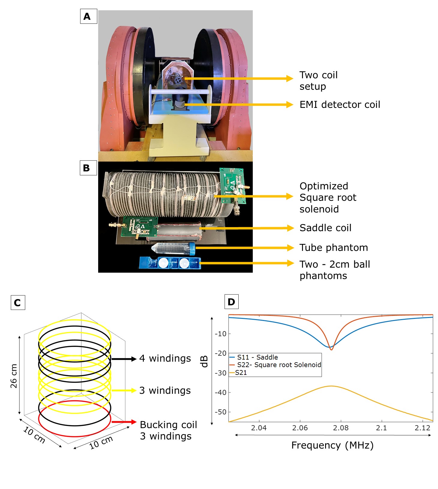
Figure 1: A.)
The 47.5mT scanner – the imaging coils are placed within a copper shielded box
and the detector coils placed outside are used for EMI suppression.
B.) BS Encoding
(square-root solenoid) and imaging (saddle) coils along with the tube phantom
and two-ball phantom. C.) Winding pattern of optimized square root solenoid. red– Bucking
coil with 3 windings, yellow – 3 windings, black – 4 windings. D.) S-
parameters for both coils and their decoupling (S11 - Saddle coil : -18dB , S22- Square-root solenoid: -17.5dB , S21: 36dB).
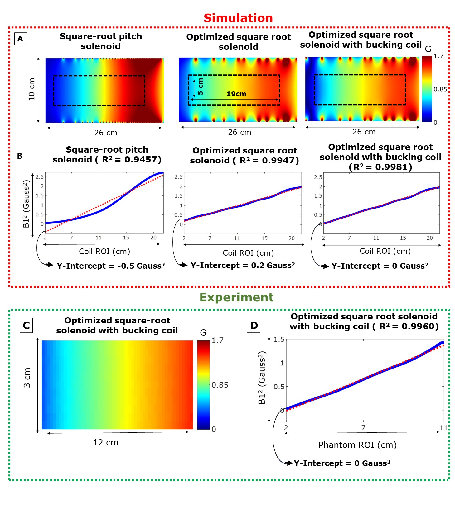
Figure 2: A)
Square root solenoid simulation - Left to Right – Regular square root pitch solenoid,
optimized square root solenoid and optimized square root solenoid with Bucking
coil windings (all with same number of windings, except the Bucking coil windings). B) Average B1+2 profile in ROI shown in A for three
coils along with a linear fit with its R2 and y-intercept values. C.) Experimental B1+ map using a tube phantom in
the optimized square root coil with bucking coil windings. D.) Average B1+2 profile for map shown in C along with
a linear fit with its R2 and y-intercept values.
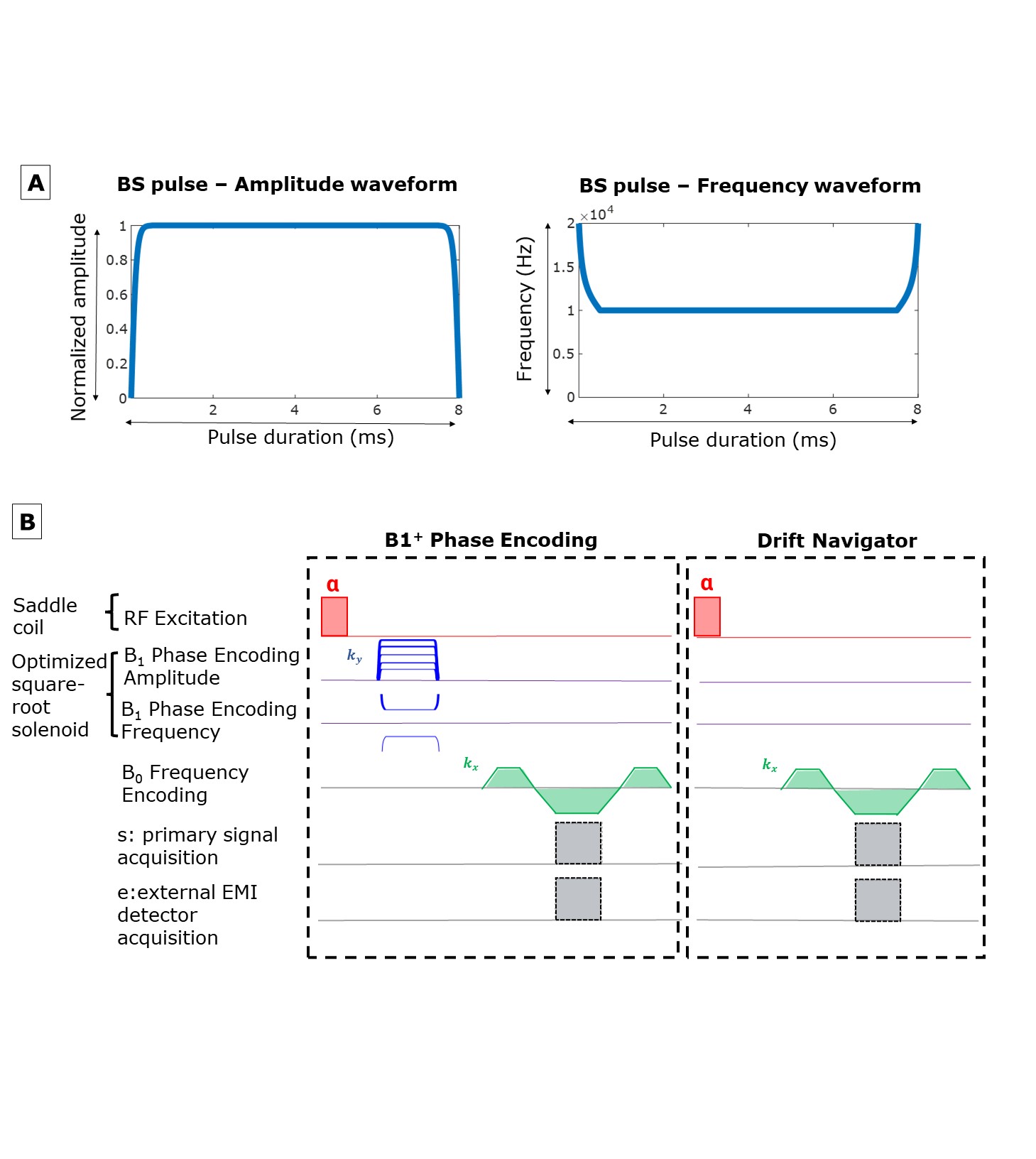
Figure 3: A.)
The BS pulse used for Phase encoding - Left to right – Amplitude and Frequency
B.) A 2D GRE sequence for B1+ phase encoding using the uniform saddle coil for
the imaging excitation pulse and the square root solenoid for encoding. A Navigator is interleaved to acquire data to adjust for scanner phase
drift.
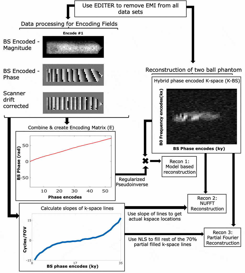
Figure 4: (Animated) Reconstruction
Pipeline: All datasets were EMI corrected and corrected for scanner phase drift
to create an encoding matrix (E). E was used to reconstruct the two-ball
phantom using its hybrid phase encoded k-space data for the Model-Based Recon (Recon 1).
NUFFT (Recon 2) and partial Fourier (Recon 3) reconstructions were done by calculating the slopes
of BS phase encodes of the tube phantom to obtain ky locations for the NUFFT.
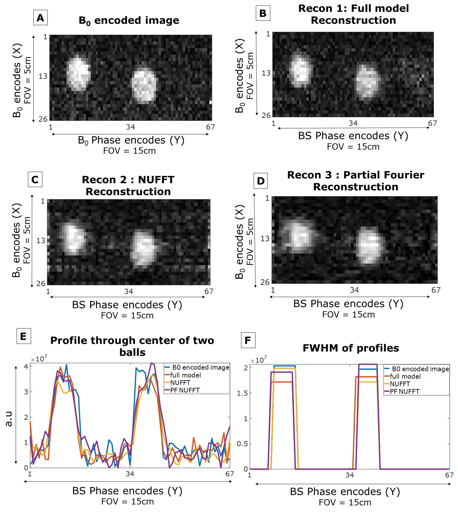
Figure 5: A.)
B0 encoded image B.) Recon 1: Full model/ empirical reconstruction C) Recon 2: NUFFT
Reconstruction D.) Recon 3: Partial Fourier reconstruction - of two-ball
phantom. E.) 1D profiles through the center of the two balls for images shown in A-D. F.) FWHM of
profiles shown in D.
DOI: https://doi.org/10.58530/2022/0062