4279
Hybrid Pair Ratio Adjustable Power Splitter using off-shelf components and easy-to-replace microstrip phase shifter1Vanderbilt University Institute of Imaging Science, Nashville, TN, United States, 2Department of Radiology and Radiological Sciences, Vanderbilt University, Nashville, TN, United States, 3Biomedical Engineering, Vanderbilt University, Nashville, TN, United States, 4Electrical and Computer Engineering, Vanderbilt University, Nashville, TN, United States
Synopsis
A low loss ratio adjustable power splitter (RAPS) was designed with a Wilkinson Splitter, a pair of transmission lines, and a hybrid coupler. There are some potential issues with the previous RAPS: 1. Build a high-performance RAPS circuit with lumped elements is challenging and laborious at 298 MHz. 2. The 100-Ohm RF decoupling resistor poses a safety hazard to the patient. In this abstract, the Wilkinson splitter was replaced with a hybrid coupler, and the adjustable transmission lines are replaced with printed microstrip lines to mitigate the problems mentioned above.
Purpose
Add-on RF shimming device can provide more freedom to manipulate the transmit field in high field MRI by controlling more coil elements even with few large-sized and high-cost power amplifiers [1-4]. The ratio adjustable power splitter (RAPS) [5] is such a circuit that enables the control of power ratio transferred to different coils by changing the phase shift between a Wilkinson splitter and a hybrid coupler. We propose a hybrid pair RAPS (HP-RAPS) using off-shelf components and easy-to-produce and easy-to-replace microstrip phase shifters to solve challenges encountered in the previous RAPS circuit, for example, laborious manufacture process and potential safety concern due to power dissipation.Methods
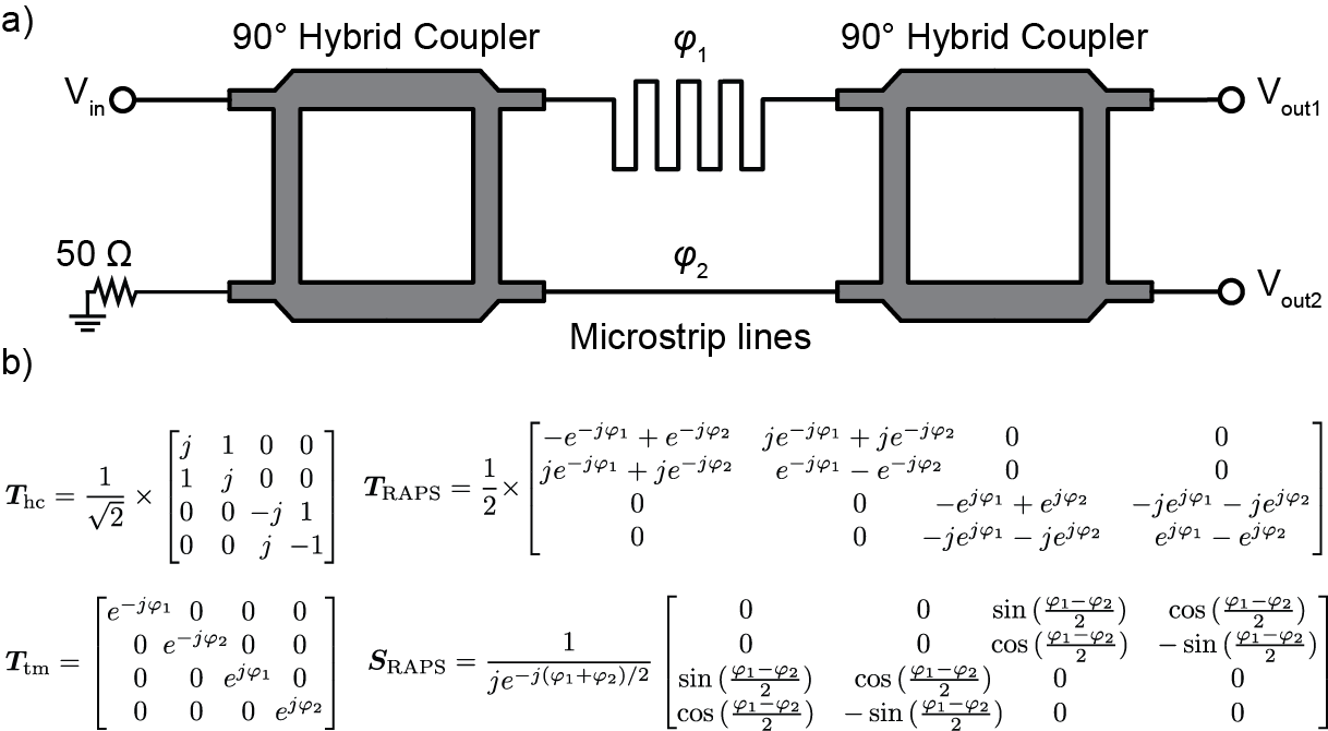
TheoryFigure 1a shows the HP-RAPS design's circuit diagram, composed of two hybrid couplers and microstrip lines between them. Figure 1b shows the derivation of power ratio between two output ports using chain transmission matrices. First, the transmission matrix of the HP-RAPS ($$$\it T_{RAPS}$$$) is calculated by multiplying three transmission matrices in series: $$$\it T_{RAPS} = T_{hc}T_{tm}T_{hc}$$$, where $$$\it T_{hc}$$$ and $$$\it T_{tm}$$$ are the transmission matrices of the hybrid coupler and microstrip lines, respectively. Then $$$\it T_{RAPS}$$$ is converted to scattering (S-) parameter matrix [5].
Design Consideration
Unlike the commercial non-magnetic power splitter, usually bulky and high-cost (>$1K), a non-magnetic hybrid coupler only costs $20-$60. It can be provided in small sizes (for example, the coupler used in this abstract is only 1.27x3.53x0.36 cm3). By carefully choosing the models for special applications, the insertion loss and amp/phase imbalance could be <0.1 dB and <0.1 dB/2 degrees, respectively. The only component we need to design and fabricate is the microstrip lines. The phase difference between the two traces is realized by designing one trace to be straight (less phase delay, fixed) and the other meander (more phase delay, variable). The length difference between the two lines is achieved by varying the total length of the meandering.
Simulation
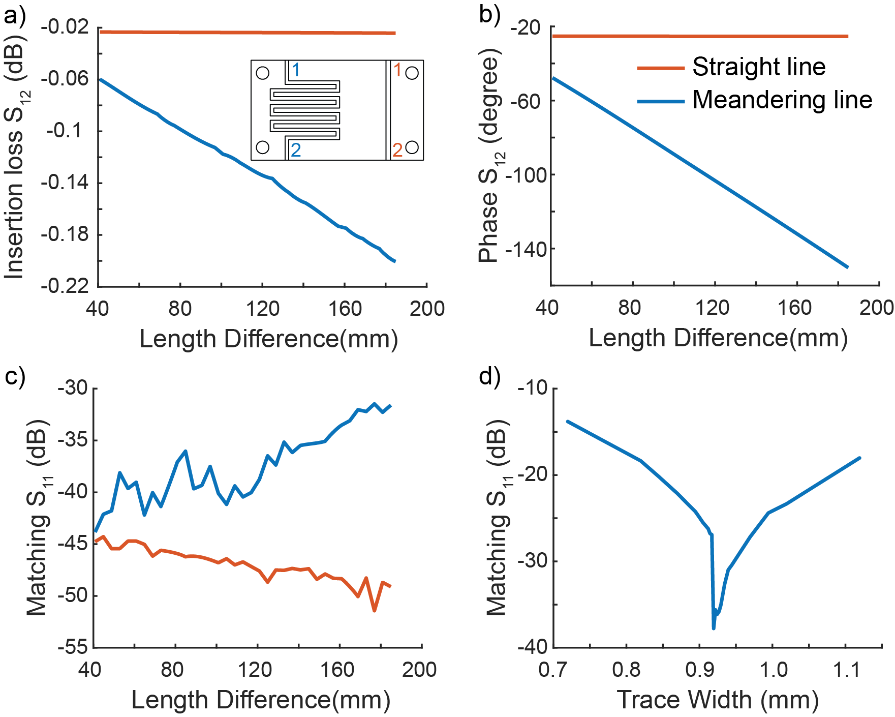
We first simulated a pair of microstrip lines with one straight line and one square meandering line with the Ansys HFSSEM package (Ansys, Canonsburg, PA). We exported the S-matrix of these pairs of microstrip lines into Ansys Designer. With the S-matrix of hybrid couplers based on the manufacturer's datasheet, we simulated the S-matrix of the whole HP-circuit. The impedance and phase shift of a straight microstrip line is straightforward and can be found in textbooks[6]. For a Rogers 3010 board with a dielectric constant of 10.2 and thickness of 1.27 mm, the optimal trace width for 50 Ohm is 1.18 mm. However, for the meandering line, its impedance and phase shift deviated from the standard equations and need to be corrected [7]. In this work, to make sure the microstrip line has a Characteristic impedance of 50 Ohm, we investigate the impedance variations with trace widths from 0.72 mm to 1.12 mm.
Fabrication and Evaluation
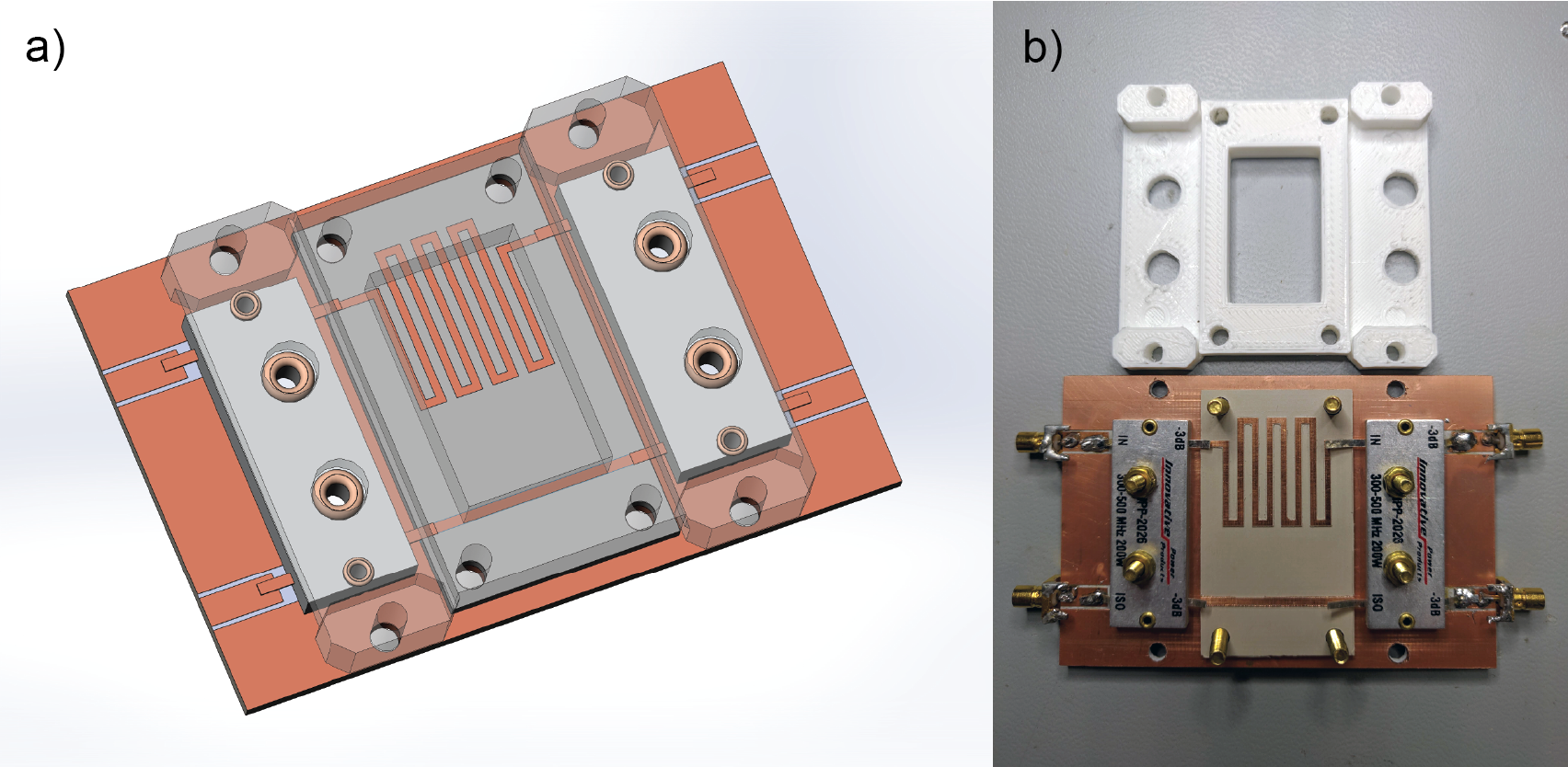
The HP-RAPS comprises a motherboard (Rogers 4003C) with two hybrid couplers (IPP2026, Holbrook, NY), a daughterboard (phase shifter board) with one straight and one meandering microstrip (Rogers 3010), and a 3D printed cover that fasten the daughterboard to the motherboard. The motherboard is fixed and served as a ground, while the daughterboard is replaceable to realize desired power split ratios. Figure 2 shows the Solidworks drawing and the photograph of an HP-RAPS with a split ratio of 1:1.
Results and Discussion
SimulationFigure 3 shows the simulated insertion loss, matching, and phase difference of the daughterboard's microstrip lines. The insertion loss increases as the microstrip line's length increase (figure 3a), but it is still only -0.20 dB when the phase delays up to 150 degrees. The straight line with calculated width (1.18mm) achieved a superior matching of -45 dB. The Characteristic impedance or the matching of the meandering line depends on its size and length. However, we found a universal width (0.92 mm) that can achieve acceptable matching performance with any lengths (<-30 dB).
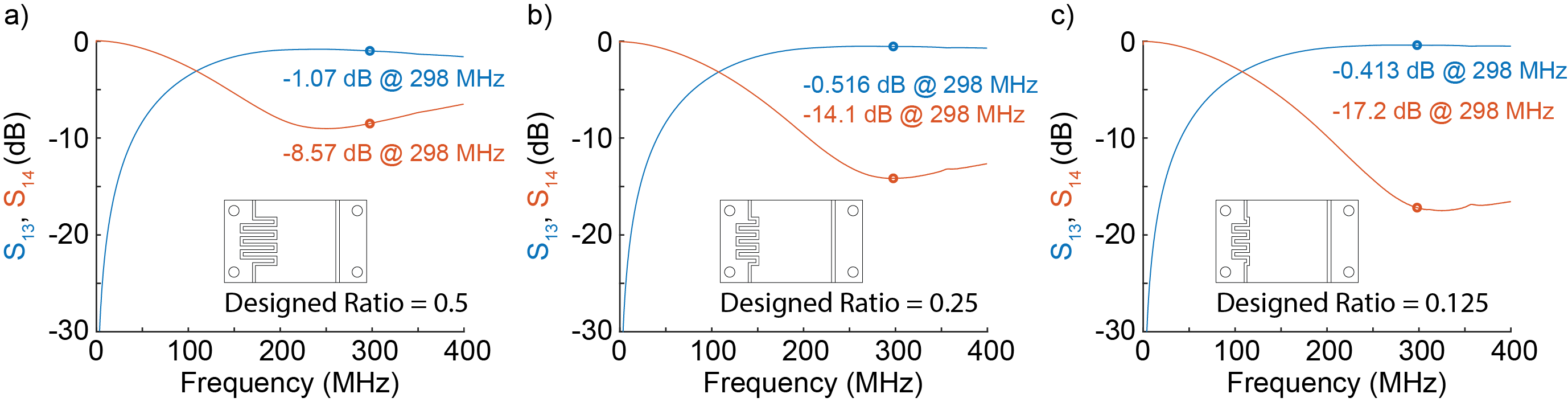
Fabricated device bench test
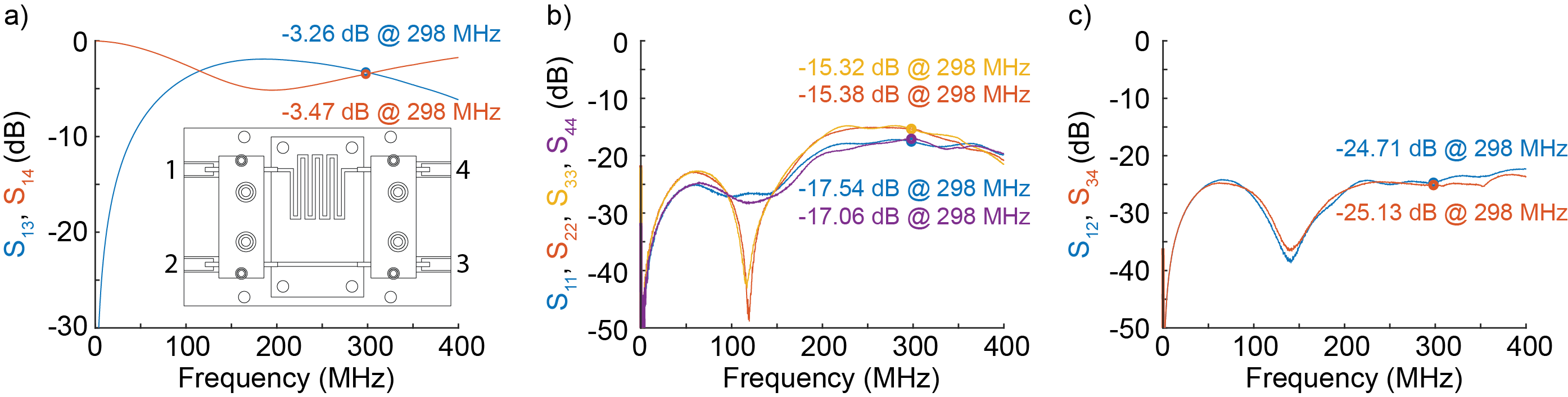
The bench test results of boards are shown in Figures 4 and 5. The ratios of the two output by input from port 1 are consistent with the equations in Figure 1b and the simulation results in Figure 3b. Compared to the previous coaxial cable phase shifter design, the microstrip design considerably eased the production procedure and improved accuracy. The insertion loss for all the tested boards is approximately 0.33 dB. The non-perfect impedance matching (about -16 dB) causes partial insertion loss, which can be further reduced. The insertion loss is less compared to the previous RAPS circuit (averaged 0.54 dB) [1] is mainly because of the removal of SMA connectors. The isolation between each board is good (about -25 dB). The 50-Ohm isolation resistor is designed to be moved far away from the circuit with a standard cable without crossing any components.
Conclusion
A Hybrid Pair Ratio Adjustable Power Splitter (HP-RAPS) was theoretically analyzed, designed, simulated, fabricated, and bench test. In addition to benefits inherited from the previous RAPS circuit (high-power handling, compact size, low-loss, and ratio-adjustable), the new HP-RAPS is more comfortable to build, easier to reproduce, and exhibits a lower power loss (0.33 dB for the whole board).Acknowledgements
This project is supported by NIH R01 EB016695.References
1. Cao Z, Yan X, Grissom W A. Array-compressed parallel transmit pulse design. Magn Reson Med. 2016;76:1158-1169.
2. Yan X, Cao Z, Grissom W A. Ratio-adjustable power splitters for array-compressed parallel transmission. Magn Reson Med. 2018;79:2422–243.
3. Yan X, Cao Z, Grissom W A. Experimental implementation of array-compressed parallel transmission at 7 Tesla. Magn Reson Med. 2016;75:2545-2552.
4. Sun C, Patel K, Wilcox M, et al. A retrofit to enable dynamic B+ 1 steering for transmit arrays without multiple amplifiers. Magn Reson Med. 2020;00:1–13.
5. Frei J, Cai X, Muller S, Multiport S-Parameter and T-Parameter Conversion With Symmetry Extension. IEEE Trans Microw Theory Tech. 2008;56:2493–2504.
6. Microwave Engineering, 4th Edition | Wiley, Wiley.com. https://www.wiley.com/en-us/Microwave+Engineering%2C+4th+Edition-p-9780470631553. Accessed December 15, 2020.
7. Nakamura T, Sekine T, Yokokawa S. An analysis of meandering lines. Electron Commun Jpn Part Commun. 1986;59:99–106.
Figures