4277
STAR MRI With Non-Magnetic, Integrated Circulator based on Switched Transmission Lines1Columbia University, New York, NY, United States, 2University of Minnesota, Minneapolis, MN, United States, 3Arizona State Univeristy, Tempe, AZ, United States
Synopsis
Traditional MRI employs time division duplexing between the receiver (RX) and transmitter (TX) to avoid RX saturation from TX self-interference. Large switching time between the TX and RX modes demands large TX power and constricts the imaging to tissues with large relaxation times. In this work, we propose a magnetic-free, switch-transmission line circulator which is fully compatible with MRI systems and achieve simultaneous transmit and receive (STAR) MRI.
Introduction
Transmit (TX) and receive (RX) in a conventional magnetic resonance imaging (MRI) system are duplexed in time to protect the RX from the strong TX self-interference (SI). Large switching times between the TX and the RX modes demands strong radio frequency (RF) signal to be incident on the tissue and also limits its application in imaging tissues with very short relaxation times. Simultaneous transmit and receiver (STAR) MRI, on the other hand, can address these issues by operating TX and RX at the same time, potentially reducing the TX peak-power requirement to 1% of the conventional MRI systems [1], and enabling signal accusation with ultra-short relaxation times [2]. In-band STAR systems are also explored in wireless and radar systems in form of full-duplex wireless to double the channel capacity and FMCW radar systems for efficient target detection. However, achieving large TX SI suppression is a critical bottleneck in all of these STAR systems [2],[3]. Typically, >100dB SI suppression is required and is achieved across multiple stages including antenna interface, analog/baseband cancellation, and digital cancellation [2],[3]. Circulators and reciprocal hybrids are commonly used as antenna interfaces. Traditionally circulators are implemented using ferrite materials which are incompatible with MRI systems. Recent research has shown the possibility of realized integrated circulators without using magnetic materials through spatio-temporal conductivity modulation [4]-[7] . Building on our work on differential MRI circulator at 167MHz [7], in this work we present a non-magnetic, switched transmission-line based circulator with single-ended ports thereby omitting the need for differential-single-ended baluns and their losses. Additionally, we demonstrated the capability of in-built isolation tuning by altering the clock waveforms. Our circulator which is designed to operate with a 1.5 Tesla eight-channel TEM head coil and achieves a transmission loss of 6.1dB and 5.8dB in the TX and the RX paths respectively, while achieving a TX-to-RX isolation of 75dB at 64MHz.Operation Principle of the Switched Transmission Line Circulator
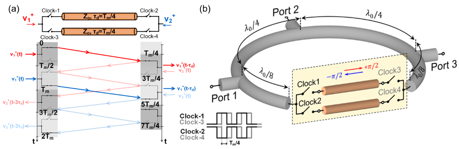
Fig. 1(a) shows the circuit diagram and the operation of a single-ended phase-nonreciprocal element which was leveraged to realize a non-reciprocal circulator shown in Fig. 1(b). It consists of two transmission-line segments which are sandwiched between switches that are modulated using square wave clocks which are staggered modulated signals with a modulation period Tm. The switches on the left and right are staggered by Tm/4 which is also equal to the delay of the transmission lines. In the forward direction, the signal experience the delay of the transmission line Tm/4, while in the reverse direction, the signal experiences a delay of 3Tm/4 [5]. At input frequencies which are multiples of the modulation frequency, this network imparts a phase of ±90o in the forward/reverse directions, thereby realizing a non-reciprocal phase shift of 180o, also known as a gyrator. This gyrator was then embedded within a 3λo/4 (3λo = λm) ring with 3 ports which are λo/4 apart to realize a 3-port circulator similar to [6](see Fig. 1(b)).Prototype Design and Measured Results
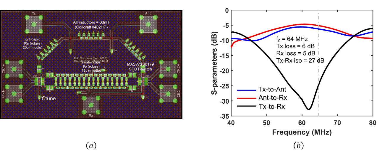
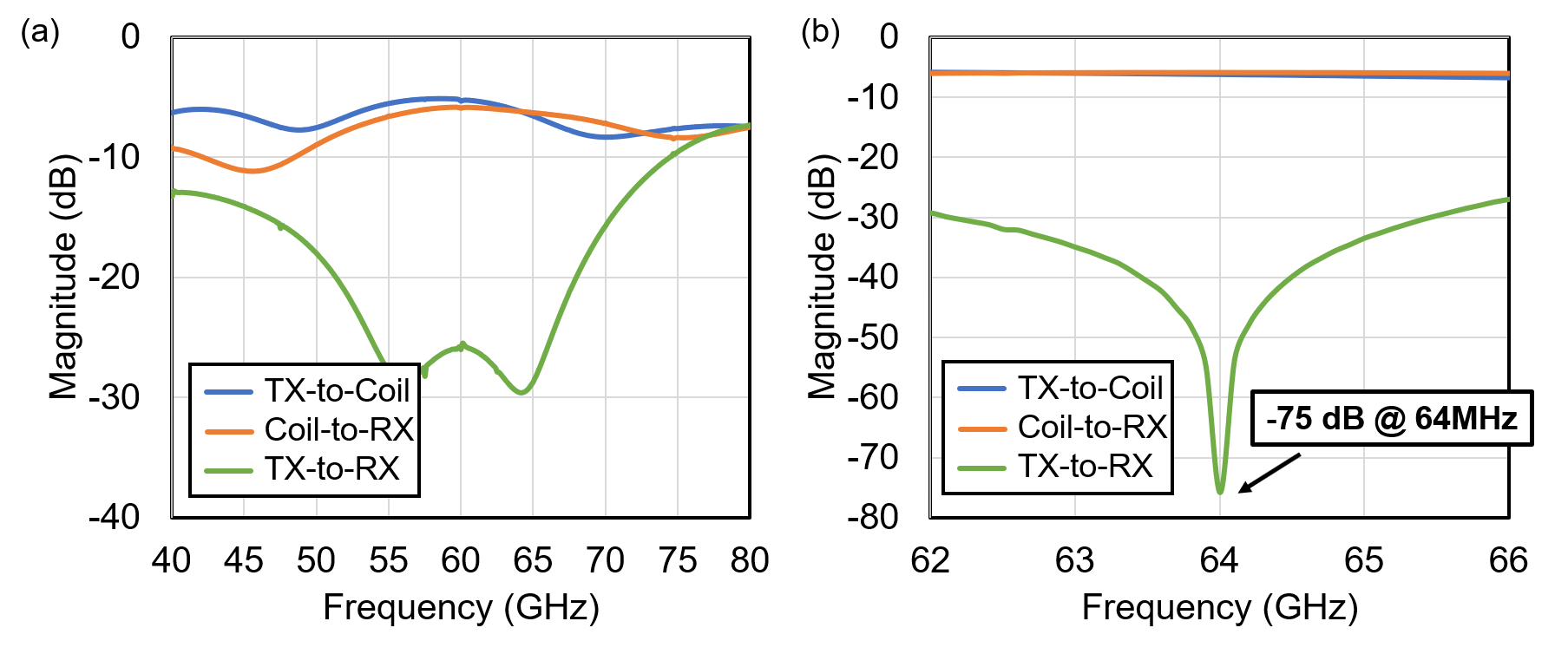
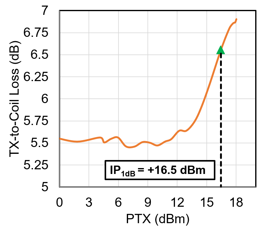
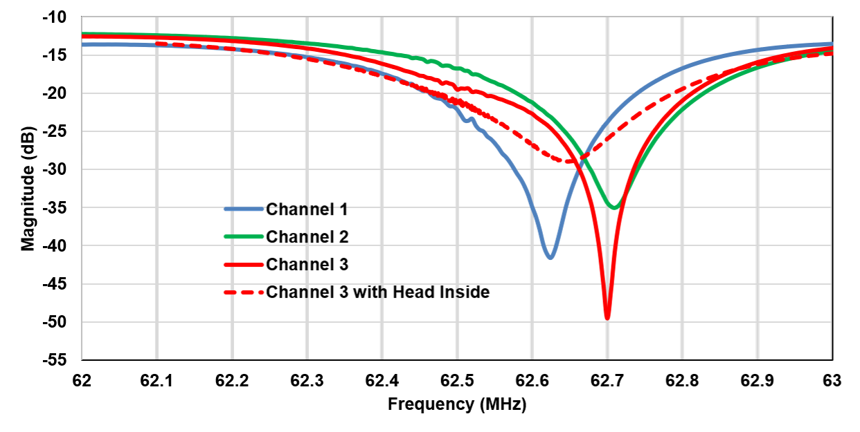
Fig. 2 depicts the PCB layout of the switched transmission line circulator. The transmission lines within the circulator are implemented using miniaturized LC sections and the switches are implemented using SPDT switches. The square wave clocks to the switches are provided through arbitrary waveform generators (AWG). For an operating frequency of 64MHz corresponding to the resonance frequency of a 1.5T MR coil, the switches are supposed to be modulated at 21.33MHz. However, the bandwidth of the AWGs was limited to 20MHz, hence a sub-optimal modulating frequency of 20MHz was adopted. The measured transmission and isolation scattering parameters of the circulator are plotted in Fig. 3(a). We measured an insertion loss of -6.1dB and -5.8dB in the transmit-to-coil and coil-to-receive paths with a -1dB bandwidth of 13MHz. The circulator can be tuned for high isolation at 64MHz by controlling the staggering and duty cycles of the modulation clocks. When tuned to 64MHz, we measured high isolation of +75dB with a 40dB isolation bandwidth of 1.1MHz (Fig. 3(b)). Sub-optimal switching frequency and large rise time in the clock waveforms has resulted in an additional ~3dB insertion loss in each path and these which can be recovered by adopting a better clock generation circuit [6]. The transmission path compresses by 1dB at a TX power level of +16.5dBm or 44mW (Fig. 4). Fig. 5 depicts the TX-to-RX isolation of the circulator when terminated with 3 of the 8 available channels in a 1.5T TEM head coil. The isolation across these channels ranges from 35dB – 50dB. When the MR coil is loaded with a human head, the TX-to-RX isolation degrades to ~30dB, which can be re-tuned to ~45dB by controlling the clocking scheme.Conclusion and Future Work
In this work, we have demonstrated a switched-transmission line circulator that can be used in a STAR MRI system. The insertion losses of the circulator were limited due to the limitations of the clock generation setup and can be improved significantly with integrated clocking solutions. Furthermore, the high isolation is sensitive to the MR coil’s impedance and an adaptive closed-loop isolation tuning mechanism is currently in progress. Integrating this circulator with additional stages of analog and digital cancellation is also in progress.Acknowledgements
This work was supported by the National Institutes of Health grants U01 EB025153 and P41 EB015894.References
[1] Idiyatullin D, Suddarth S, Corum CA, Adriany G, Garwood M. Continuous SWIFT. J Magn Reson., 220:26-31 (2012).
[2] Ozen A., Atalar E., Korvink J., and Bock. M. In vivo MRI with Concurrent Excitation and Acquisition using Automated Active Analog Cancellation. Sci. Rep. 8, 10631 (2018).
[3] Katti S. Full duplex radios. Proc. 9th ACM Conf. Emerg. Netw. Exp. Technol. (CoNEXT). 375–386 (2013).
[4] Reiskarimian N., and Krishnaswamy H. Magnetic-free non-reciprocity based on staggered commutation. Nature Commun. 7,11217 (2016).
[5] Nagulu A. Nonreciprocal Components Based on Switched Transmission Lines. IEEE Trans. Microw. Theory Techn. 66, 4706-4725 (2018).
[6] Nagulu A., and Krishnaswamy H. Non-Magnetic CMOS Switched-Transmission-Line Circulators With High Power Handling and Antenna Balancing: Theory and Implementation. IEEE J. Solid-State Circuits 54, 1288-1303 (2019).
[7] Yuksel H., A Non-Magnetic Staggered Commutation Based Circulator to Achieve Time-Efficient Simultaneous Transmit and Receive (STAR) MRI. ISMRM 2020.
Figures