4272
Triggering pulse generation by non-contact monitoring of heart rate using an antenna with 600 MHz resonance1Advanced MRI Development PJ Team, Canon Medical Systems Corp., Kawasaki, Japan, 2Advanced Technology Research Department, Research and Development Center, Canon Medical Systems Corp., Kawasaki, Japan, 3Medical Products Technology Development Center, R&D Headquarters, Canon Inc., Tokyo, Japan
Synopsis
New non-contact cardiac and respiratory gating method have been developed, which includes an antenna monitoring heart and respiration movement, and independent triggering pulse generation unit with signal processing software. The resonance frequency of the dipole antenna was tuned to around 550MHz on the chest. The triggering pulse generation unit detected and digitized the S11 signals from the antenna. IIR filter removed the low frequency component and a template matching technique was used to seek the triggering points at the inflection point of filtered waveform. As a result, the prospective gating cardiac imaging was successfully performed for volunteers.
Introduction
Cardiac and respiratory gating methods with skin contact electrodes and bands are applied for conventional cardiac and body imaging. But, non-contact cardiac and respiratory gating methods have been developed recently to improve patient comfortableness and workflow. The methods using phased array coil profile and electric characteristics of the tissue are feasible without sequence limitation1,2, but need complicated hardware. In this work, we have developed an antenna3,4 monitoring heart and respiration movement, an independent triggering pulse generation unit including signal processing software for seeking the triggering points, and performed a volunteer study of prospective gating cardiac imaging.Method
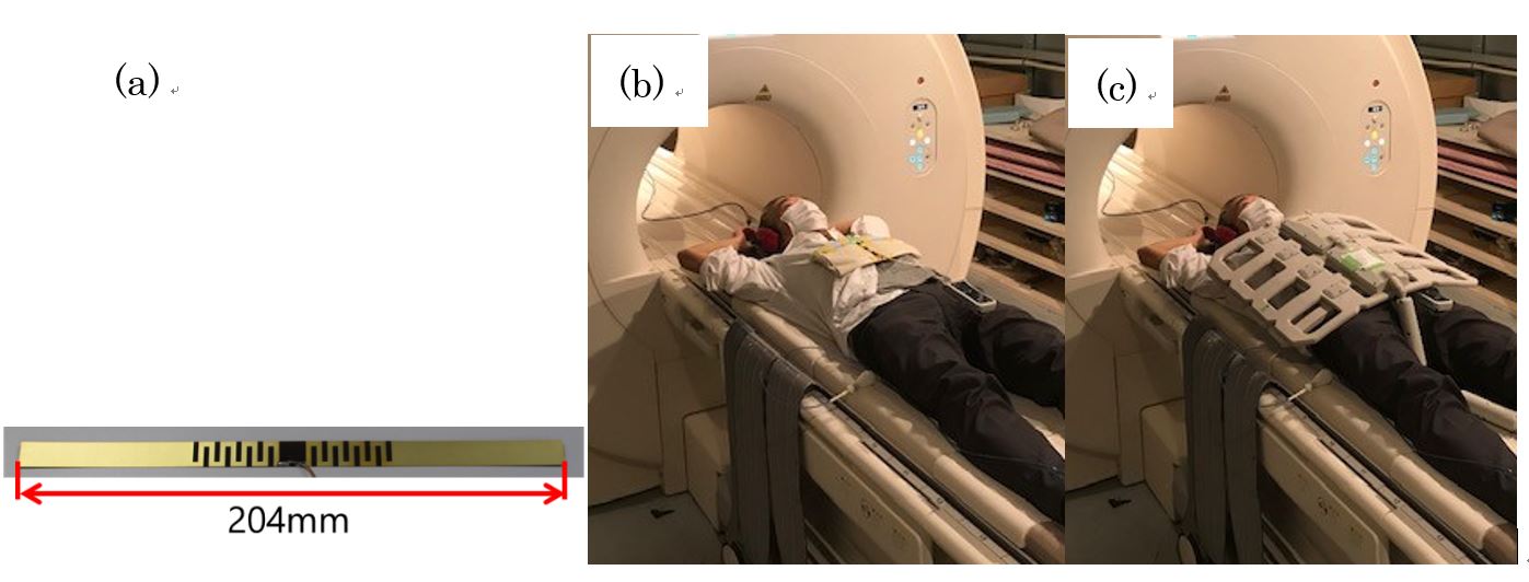
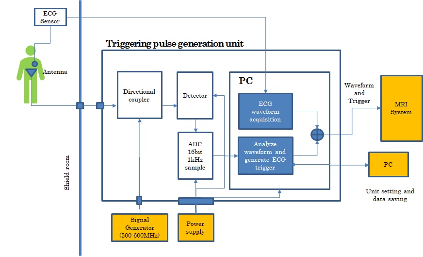
Canon 3T system was used with the body and spine array coils to evaluate this triggering system. The antenna used for the non-contact heart rate monitor is a meander shape dipole antenna shown in figure 1(a). The resonance frequency of the dipole antenna in free space is 600MHz, and when the antenna is placed on the patient chest with a pad (1 cm thickness), the resonance frequency of the antenna changes to around 550MHz (Figure 1(b)). The body array coil was set on the antenna for cardiac imaging (Figure 1(c)). The S11 time response data of the antenna at the resonance frequency are monitored via a high-pass filter (112dB) to remove RF pulses. The frequency of the Signal Generator is adjusted in around 550MHz for each volunteer to find larger deviation of S11 signals due to a cardiac cycle.Figure 2 shows a triggering pulse generation unit, which detects the S11 signals and convert it to digital data. A log detector was used to gain dynamic range. The triggering pulses were generated by triggering pulse generation algorism in the PC, send to the MRI system and compared to the conventional ECG waveform from ECG electrodes.
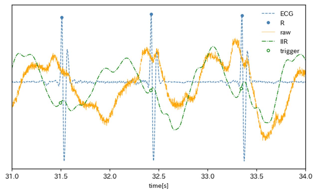
An algorithm to generate triggering pulses at the same timing as the R-wave in ECG, utilizes the characteristics of S11’s waveforms. In this study, we concentrated generating cardiac triggering pulse. The low frequency component derived from abdominal (respiratory) movement was removed by an infinite impulse response (IIR) filter with a passband from 1 to 15 Hz. Figure 3 shows the waveforms of an ECG (blue), antenna signals before IIR filter (orange) and IIR filtered antenna signals (green). Since the inflection point of the IIR filtered waveform almost coincide with the R-wave of the ECG, a template matching technique was used to seek the triggering points at the inflection point. The template is created using the waveform for the first 10 seconds or so and is continuously updated.
Results and Discussion
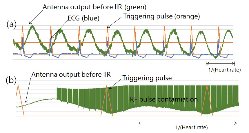
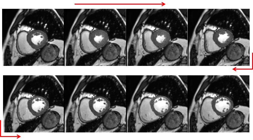
The algorithm for generating the trigger points from the S11 waveform was evaluated using the S11 and ECG waveforms obtained by changing the antenna positions and employing some volunteers outside the magnet. As a result, the variations of mean value and standard deviation of the generated trigger point and the R wave of ECG were 0.3 ms to 20.6 ms and 5.7 ms to 15.5 ms, respectively. As a result, the mean value and dispersion value of the generated trigger point and the jitter of the R wave of ECG were 0.3 ms to 20.6 ms and 17.3 ms to 46.6 ms, respectively. The cause of this deviation depends on the SNR and shape of the S11 waveform, which are affected by the arrangement of the antenna, the physique of the individual, and the frequency setting.In figures 4 and 5, the results of a volunteer study are shown. Figure 4(a) shows the waveforms of the S11 before IIR filter (green), the generated triggering pulses (orange) and ECG (blue) obtained from a volunteer before the imaging study. The jitters between the R-waves and the trigger signals were a mean value and standard deviation of the jitters were -52.6msec and 19.2msec, respectively. The deviation of the trigger points with respect to the R wave was large. Multiple inflection points were recognized for some volunteers, and this time the trigger was generated at the inflection point deviated from the R wave peak. In the evaluation outside the MRI device, only the inflection point that coincided with the R wave peak was recognized, stably detected, and a trigger was generated. In the future, it will be necessary to modify the algorithm so that the correct trigger point can be searched even when multiple inflection points are recognized. Figure 4(b) shows these waveforms when retrospective gating cine sequence started. Even if RF pulse contamination appeared, the triggering pulses were produced at stable timing and it was favorably obtained prospective gating cardiac images (Figure 5). We could successfully perform two volunteer’s cine imaging.
Conclusion
In this study, we showed that cardiac gating imaging is possible with a simple configuration using a high-frequency antenna and a triggering pulse generation unit. This method is promising to eliminate attaching electrodes and to enable gating imaging of the heart with a relatively simple configuration.Acknowledgements
No acknowledgement found.References
[1] Schroeder L, Wetzl J, Maier A, et al. A novel method for contact‐free cardiac synchronization using the pilot tone navigator. In Proceedings of the 24th Annual Meeting of ISMRM, Singapore,2016. p. 410.
[2] Jaeschke S, Robson MD, Hess AT. Cardiac gating using scattering of an 8‐channel parallel transmit coil at 7T. Magn Reson Med. 2018;80:633–640.
[3] T. Ohishi, Investigation of antenna effect on non-contact monitoring of heart and respiration rate. Proc. ISMRM 27 (2019).
[4] T. Ohishi, Investigation of appropriate frequency band and antenna for non-contact monitoring of heart and respiration rate. Proc. ISMRM 28 (2020).
Figures