4268
MR safe electromagnetic direct current motor1Department of Radiology and Imaging Sciences, University of Utah, Salt Lake City, UT, United States
Synopsis
Combining the unparalleled soft-tissue imaging capabilities of MR imaging with the precision of robotic-assisted surgeries has the potential to revolutionize image-guided surgical interventions. However, strong magnetic fields generated by the MR system prevent the use of conventional robotic servo motor technologies. Here we present a direct current electromagnetic motor design that uses the electromagnetic interaction between the MR B0 field and currents in the rotor windings to generate rotational mechanical actuation. The motor stall torque and interactions caused by simultaneous motor operation and MR imaging are characterized. This new motor may be useful for robotic assisted interventions performed under MR-guidance.
Introduction
Combining the unparalleled soft-tissue imaging capabilities of MR imaging with the precision of robotic-assisted surgeries has the potential to revolutionize image-guided neurosurgeries1,2, tissue biopsies3–6, and prostate cancer brachytherapy treatments7,8. However, the strong magnetic field of the MR system limits the use of conventional robotic servo motor actuators near the imaging region. Conventional electromagnetic motors experience significant forces near strong magnetic fields—making them potential projectile hazards. The permanent magnets, ferromagnetic actuator components, and lead wires can degrade image quality by disrupting the magnetic field homogeneity and by introducing radiofrequency noise into the shielded scanner room. Several actuator strategies developed to overcome these challenges include the use of piezoelectric1,9 and pneumatic10,11 motors. However, the added complexity, non-traditional nature, and cost of these actuator systems have limited their adoption and use to a small number of investigators.In this work we present a novel direct current (DC) electromagnetic motor design that uses the electromagnetic interaction between the B0 field of the MR system and electrical currents in the rotor windings to achieve a rotational mechanical actuation. A prototype motor was built using non-magnetic components and its basic electrical and mechanical properties were characterized. A preliminary evaluation of the interactions that occur during simultaneous motor operation and MR imaging was performed.
Methods
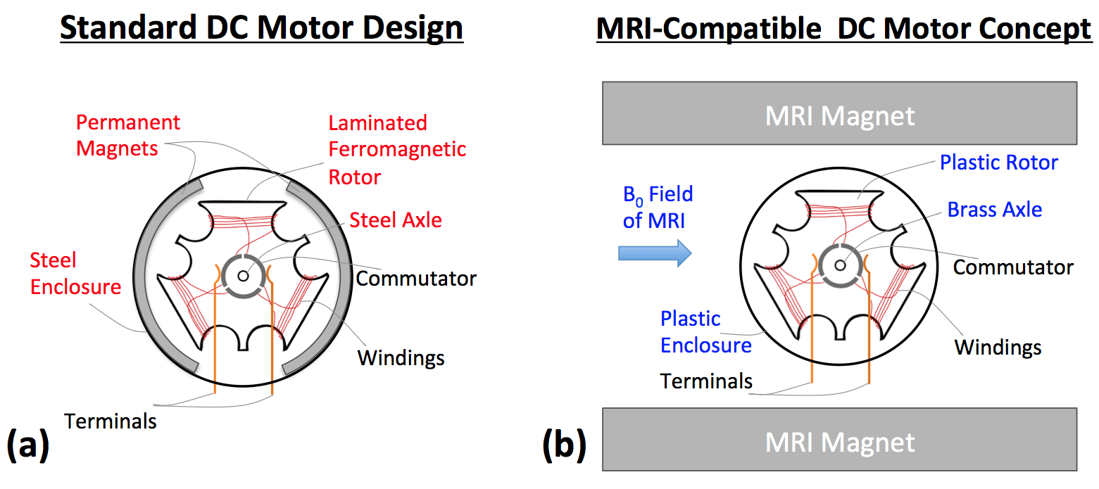
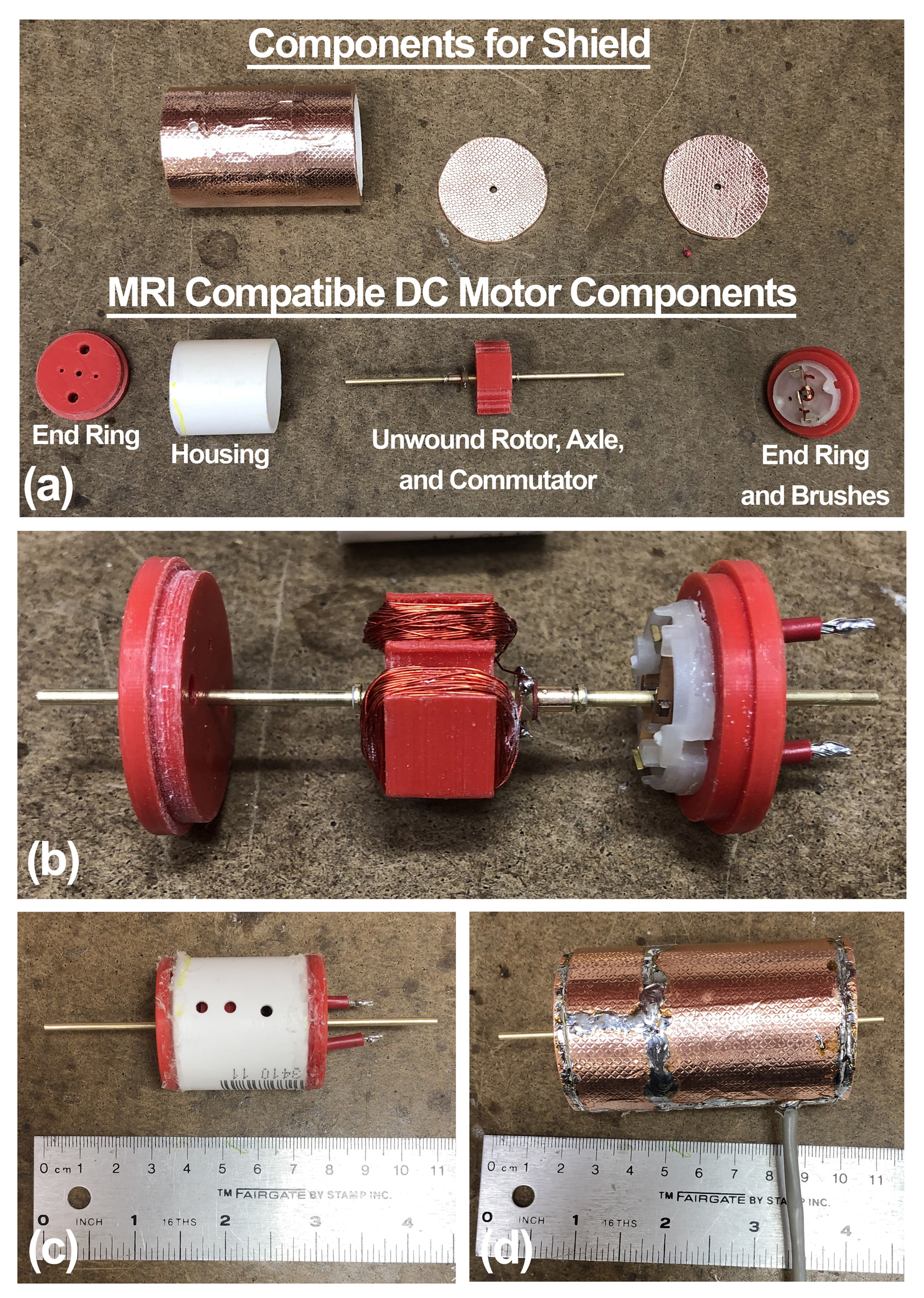
A standard permanent magnet DC motor design is shown in Figure 1a. The rotor, axle, and enclosure are ferromagnetic. Two permanent magnets generate a static field that interacts with the currents in the rotor windings. The MR safe motor design replaces these ferromagnetic and magnetic components. Plastic or brass counterparts replace the ferromagnetic parts in Figure 1a. Instead of using permanent magnets to generate a static field, the static B0 field of the MR system is used. A schematic of this new motor concept is shown in Figure 1b. It has the same functional elements of a standard DC motor design, and yet, the use of permanent magnets or magnetic materials is not needed.A motor prototype, shown in Figure 2, was constructed and used for all experiments. The relevant parts (excluding the rotor winding and shielded twisted pair cable) are shown in Figure 2a. The motor axle consisted of a 2mm diameter brass rod. The two brushes and commutator were obtained from a disassembled 280 micro DC toy motor (3V-12V). The rotor windings consisted of three 100-turn windings made from 30 AWG speaker wire. The rotor depth was 12mm. The nearly assembled motor is shown in Figure 2b and final assembly in Figure 2c. To reduce interactions between the motor and MR system, the motor was shielded as shown in Figure 2d.
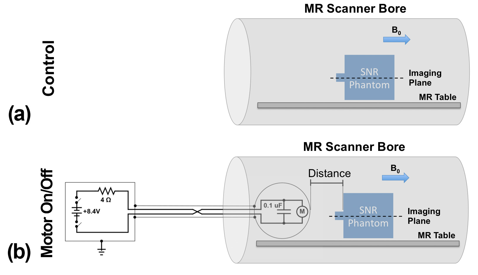
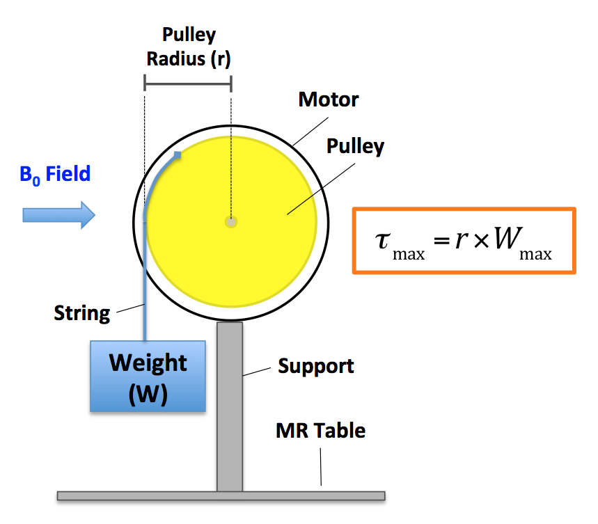
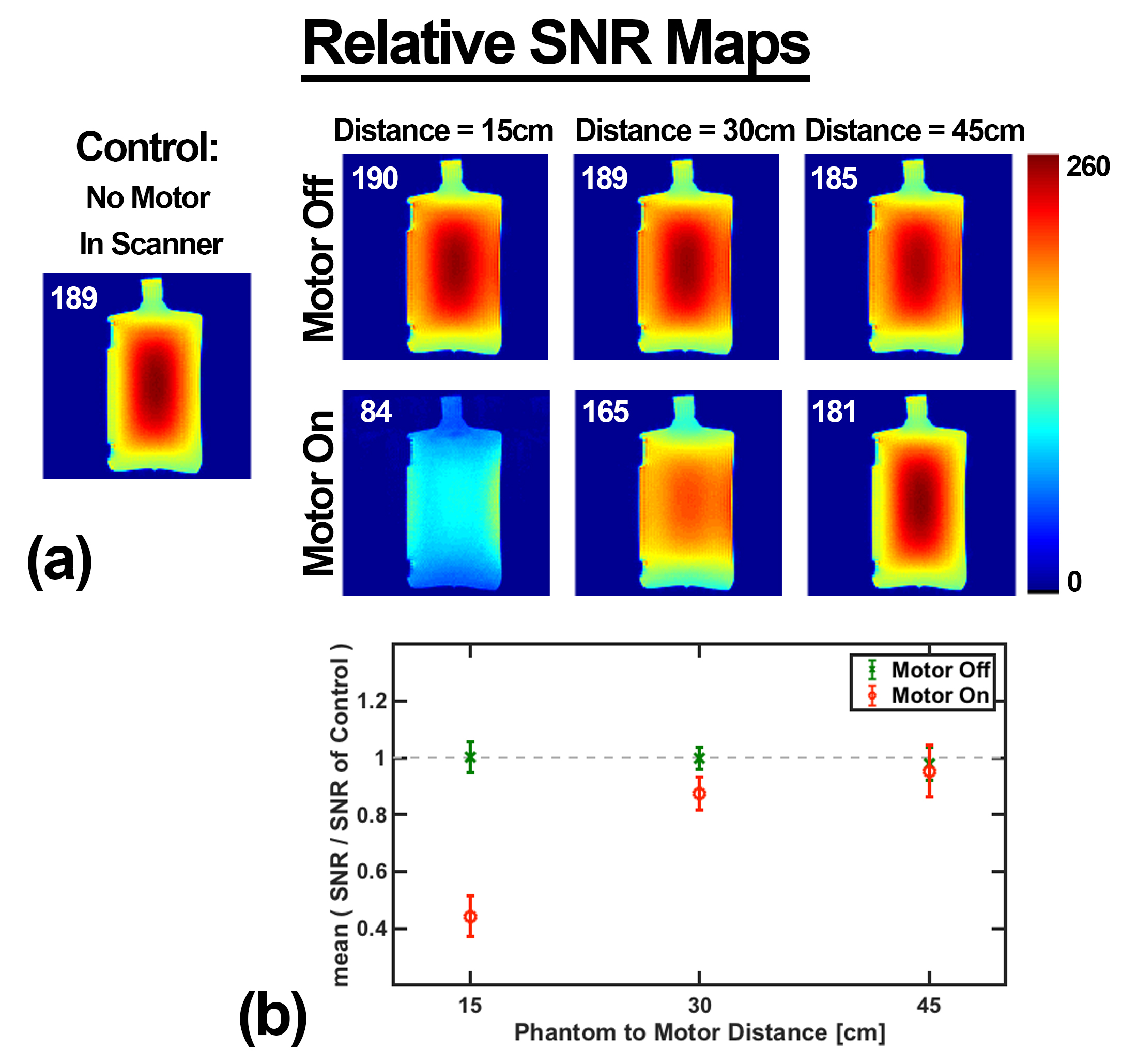
Signal to noise (SNR) imaging tests were performed to evaluate interactions between motor and MR system during imaging. The experimental tests are outlined in Figure 3 and consist of performing SNR measurements without the motor and with the motor located 15, 30, and 45cm from the SNR phantom. Imaging was performed with the motor in both on and off states using a gradient echo imaging protocol on a 3T MRI scanner (MAGNETOM PrismaFit, Siemens Healthcare, Erlangen, DE) with the following scan parameters: TE|TR = 3.58|200ms, FA = 60°, Matrix = 128×128×1, Resolution = 2×2×5mm, Bandwidth 260Hz/px, body coil was used for receive. The noise for the SNR measurement was calculated from the overscan region of each acquisition. Basic motor performance metrics were obtained using a Fluke 23 Multimeter and the stall torque measurement technique shown in Figure 4.
Results
Results from the SNR study are shown in Figure 5. When the motor was off, the relative SNR for motor-phantom separation distances of 15, 30, and 45cm was comparable to the relative SNR of the control experiment. Thus, when the motor was not running, it did not produce a noticeable effect on the relative SNR maps. However, when the motor was on, the relative SNR was 84, 165, and 181, for the 15, 30, and 45cm distances respectively. Figure 5b shows the when the motor was operating; the measured SNR was 44%, 87%, and 95% of the potential SNR for motor-phantom separation distances of 15, 30, and 45cm, respectively.When operating in the unloaded condition with 7.86V supplied across the cable leads, the motor used 0.7A of current. The measured motor stall torque was 590 g-cm at 1.1A. The measured voltage across the cable leads was 2.73V during motor stall.
Discussion and Conclusions
We have presented an MR safe motor design that exploits the electromagnetic interaction between the B0 field of the MR system and currents in the rotor windings. When the motor was off, no degradation in the relative SNR maps was measured. When the motor was operating 15cm from the phantom the measured SNR was only 44% of the SNR potential. However, when the motor was operating 30 and 45cm from the phantom, much of the SNR was recovered. While future work is needed to further reduce the interactions between the operating electromagnetic motor and scanner, these initial motor tests show great promise. The stall torque was significant given the size of the motor and low amount of current supplied at stall. This motor concept may help enable robotic assisted interventions under MR-guidance.Acknowledgements
This project was funded through NIH grants F30CA228363 and S10OD018482.References
1. Masamune K, Kobayashi E, Masutani Y, Suzuki M, Dohi T, Iseki H, Takakura K. Development of an MRI-compatible needle insertion manipulator for stereotactic neurosurgery. J. Image Guid. Surg. 1995;1:242–8.
2. Patel NA, Fischer GS, Nycz CJ, Carvalho PA, Gandomi KY, Gondokaryono R, Li G, Heffter T, Burdette EC, Pilitsis JG. An Integrated Robotic System for MRI-Guided Neuroablation: Preclinical Evaluation. IEEE Trans. Biomed. Eng. 2020:1–1.
3. Kaiser WA, Fischer H, Vagner J, Selig M. Robotic system for biopsy and therapy of breast lesions in a high-field whole-body magnetic resonance tomography unit. Invest. Radiol. 2000;35:513–519.
4. Elhawary H, Zivanovic A, Rea M, Davies B, Besant C, McRobbie D, de Souza N, Young I, Lampérth M. The Feasibility of MR-Image Guided Prostate Biopsy Using Piezoceramic Motors Inside or Near to the Magnet Isocentre. In: Springer, Berlin, Heidelberg; 2006. pp. 519–526.
5. Stoianovici D, Kim C, Petrisor D, Jun C, Lim S, Ball MW, Ross A, MacUra KJ, Allaf ME. MR Safe Robot, FDA Clearance, Safety and Feasibility of Prostate Biopsy Clinical Trial. IEEE/ASME Trans. Mechatronics 2017;22:115–126.
6. Patel NA, Li G, Shang W, et al. System Integration and Preliminary Clinical Evaluation of a Robotic System for MRI-Guided Transperineal Prostate Biopsy. J. Med. Robot. Res. 2019;4:1950001.
7. Muntener M, Patriciu A, Petrisor D, Mazilu D, Bagga H, Kavoussi L, Cleary K, Stoianovici D. Magnetic resonance imaging compatible robotic system for fully automated brachytherapy seed placement. Urology 2006;68:1313–1317.
8. Fischer GS, Iordachita I, Csoma C, Tokuda J, DiMaio SP, Tempany CM, Hata N, Fichtinger G. MRI-compatible pneumatic robot for transperineal prostate needle placement. IEEE/ASME Trans. Mechatronics 2008;13:295–305.
9. Wallaschek J. Piezoelectric Ultrasonic Motors. J. Intell. Mater. Syst. Struct. 1995;6:71–83.
10. Taillant E, Avila-Vilchis JC, Allegrini C, Bricault I, Cinquin P. CT and MR compatible light puncture robot: Architectural design and first experiments. Lect. Notes Comput. Sci. 2004;3217:145–152.
11. Stoianovici D, Patriciu A, Petrisor D, Mazilu D, Kavoussi L. A new type of motor: Pneumatic step motor. IEEE/ASME Trans. Mechatronics 2007;12:98–106.
Figures