4267
Interventional Magnetic Particle Imaging Open-bore Scanner Design1Experimental Physics V, Julius-Maximilians-University, Wuerzburg, Germany, 2Department of Diagnostic and Interventional Radiology, University Hospital, Wuerzburg, Germany, 3Department of Diagnostic and Interventional Neuroradiology, University Hospital, Wuerzburg, Germany
Synopsis
X-ray-guided endovascular interventions are important treatment approaches for many cardiovascular diseases such as myocardial infarction, stroke or occlusive peripheral arterial disease. However, they pose the risk of radiation exposure to patients and staff. Magnetic particle imaging may provide a radiation-free alternative for diagnostic and image guided treatment. A new open bore scanner concept, based on a traveling field free line and super paramagnetic iron oxide tracers is developed especially for interventional treatments. Due to the open design the scanner provides good accessibility to the patient.
Introduction
Since the first publication of magnetic particle imaging (MPI), multiple new scanner designs have been introduced to explore new applications of superparamagnetic iron oxide nanoparticles (SPIONs) in physics, chemistry as well as biological and medical research.1,2 It has the potential to be a real-time capable radiation-free alternative in clinical imaging and treatment.3,4,5,6 MPI offers great potential especially for cardiovascular imaging and endovascular therapy. Image-guided interventions, such as percutaneous transluminal angioplasty (PTA) to open up blocked blood vessels, are typically performed using x-ray based digital subtraction angiography (DSA) and fluoroscopy. DSA uses high-resolution projections in combination with iodine-based contrast agents to visualize both vasculature and interventional instruments. In proof-of-concept studies, MPI has been used to accurately measure experimental vascular stenoses, visualize interventional instruments, and perform the basic steps of established endovascular interventions such as PTA and stenting.7-11 MPI inherently offers continuous contrast projections, as only the signal of the SPION’s will contribute to signal in the imaging process. Catheter guidance could therefore be visualized throughout the treatment. This can reduce the exposure to radiation in interventional treatment by reducing the requirement for x-ray imaging. Most of the scanners developed so far only offer a small field of view (FOV) as well as a closed design. An open design, much better suited for interventions could enable access to the patient at all times. This proof-of-principle study describes a new MPI scanner concept for a bigger FOV and an explicit design feature for interventional treatment in human legs.Methods
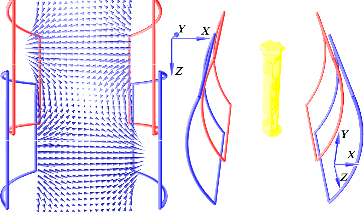
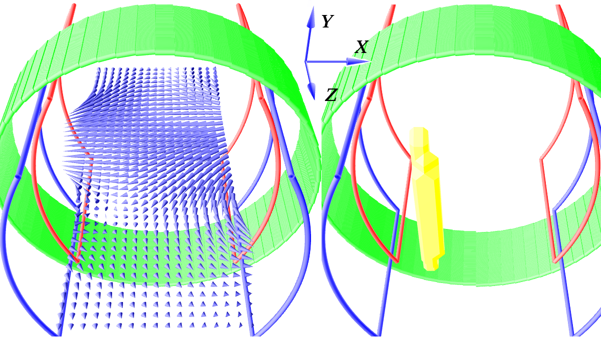
In MPI the signal is created by the nonlinear response of the SPIONs to time-varying magnetic field gradients. The response is strongest in areas, where the magnetic field currently reverses direction, which is used for signal localization. The introduced MPI scanner design is based on the traveling wave magnetic particle imaging (TWMPI) with a dynamic linear gradient array (dLGA) extending it to a field free line (FFL) approach.12-18 It converts the full response of a volume of SPIONs to a 2D projection. The FFL is a lineshaped area in the FOV, where the magnetic field gradient is strongest and the magnetic field direction changes. With sufficiently high magnetic fields and a proper open arrangement of driving coils, the FFL can be generated and moved through the FOV. Figure 1 shows the configuration of the gradient field generating coils. On the left it shows the field in the device for a static FFL with coil pairs in Helmholtz configuration and different direct current flow. The right shows the yellow FFL for different field strengths between red and blue coils, creating the FFL on a different location on the z-axis. By applying alternating currents and a phase difference of 90 degrees between coil pairs it will travel along the symmetry axis (z-axis) of the system in the time of one period of the drive frequency (f1). To move the FFL in x-direction further coils are needed. A coil creating a field in x-direction can shift the FFL from left to right. Figure 2 shows the field lines (blue arrows) on the left and the resulting FFL (yellow) on the right for a direct current. Applying an alternating current with much higher frequency (f2 >> f1) on a solenoid (green) will shift the FFL multiple times perpendicular to the z-axis motion through the device.Results
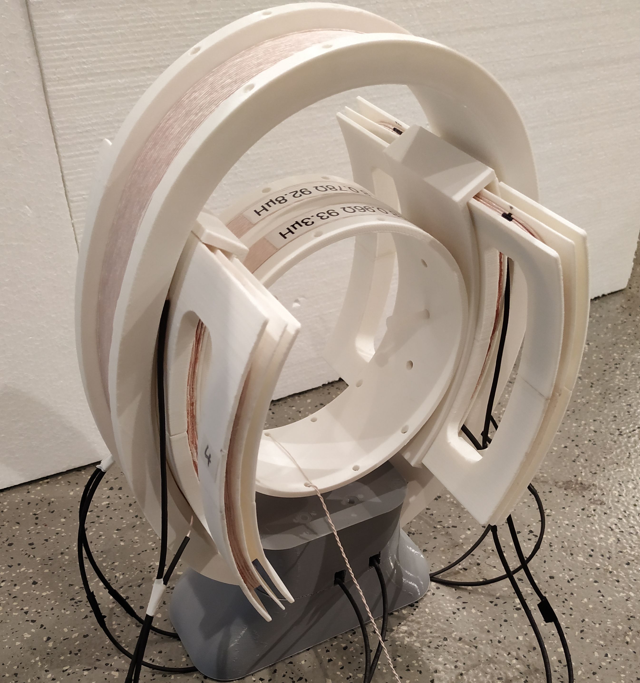
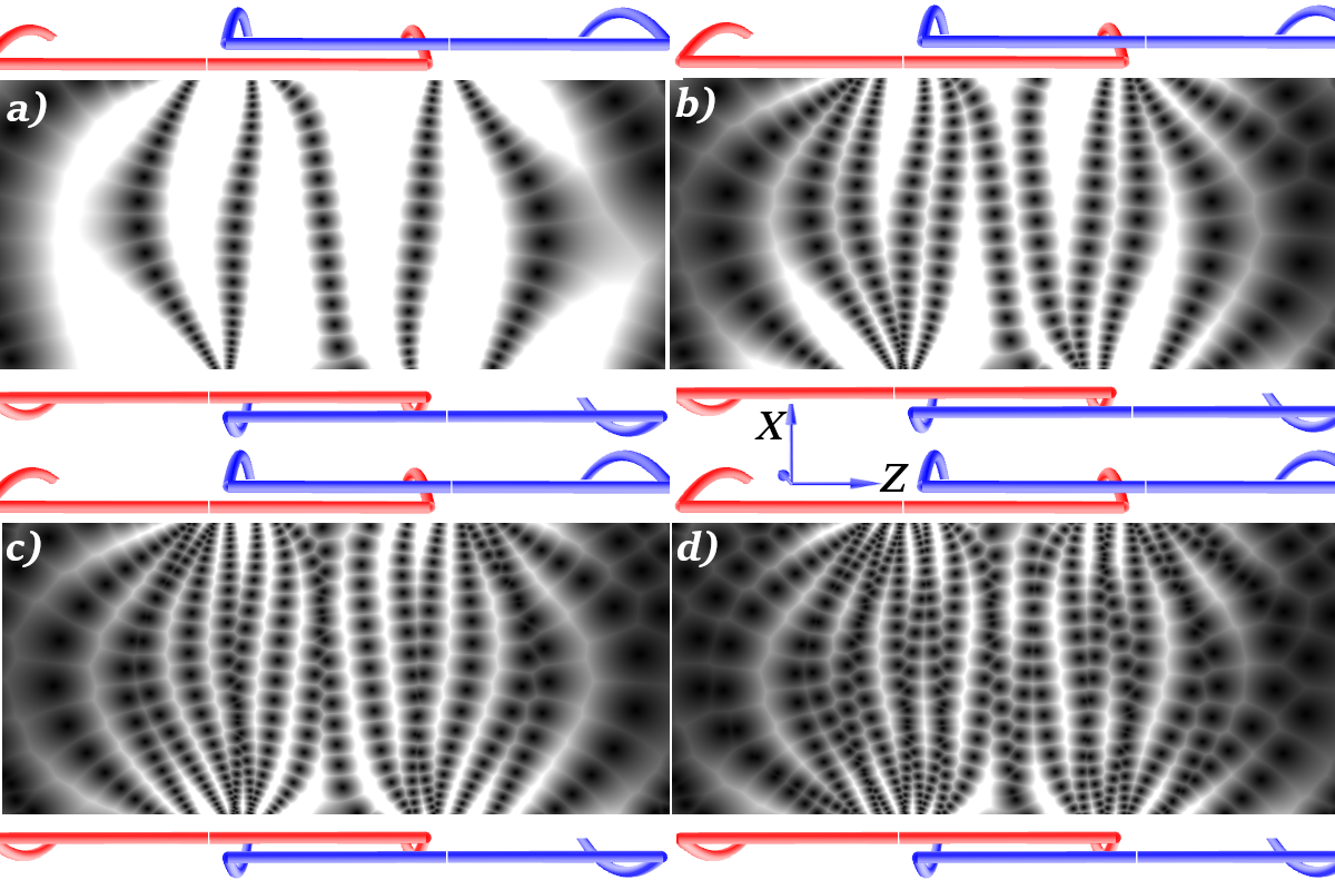
For easier handling, the coil moving the FFL along the x-axis is a solenoid, which is used as a supporting structure for the rectangular coils as well. Figure 3 shows the actual device with rectangular coils for the drive along the z-direction and the solenoid for the x-direction as well as a receiver coil. The frequency configuration is f1 = 1150 Hz and f2 = 12150 Hz. This setup allows an FFL to switch sides in the region of interest four times. In figure 4 longer scanning time for the given frequencies is shown, where the black dots are locations of the FFL at a given time, moving from the right side to the left. Because the ratio between f1 and f2 is not an even number, each pass through the device shifts the FFL through the FOV in z-direction allowing a better sampling of the FOV.Discussion
This concept system has the ability to increase the FOV by introducing additional coils to the array, it is also accessible and has a larger FOV. The challenge of the new system is the new configuration and establishment of the FFL with sufficiently strong magnetic gradients. Large distances between drive coils and positioning of the receiver coil require new filter systems and suitable low noise amplifiers to improve the signal to noise ratio with the currently used amplifiers. The Interventional MPI open bore scanner may provide a promising, radiation-free support for interventional treatment of cardiovascular pathologies.Acknowledgements
Research funding: The work was supported by the German Research Council (DFG) (grant number: VO-2288/1-1). Conflict of interest: Authors state no conflict of interest.References
1. B. Gleich & J. Weizenecker, Tomographic Imaging using the nonlinear response of magnetic particles, Nature, 435, 1214-7, 2005.
2. T. Knopp et al., Magnetic Particle Imaging: From Proof of Principle to Preclinical Applications, Phys Med Biol, 62(14), R124, 2017.
3. J. Haegele et al., Magnetic particle imaging: visualization of instruments for cardiovascular intervention, Radiology, 265, 933-8, 2012.
4. J. Salamon et al., Magnetic particle/magnetic resonance imaging: in-vitro MPI-guided real time catheter tracking and 4D angioplasty using a road map and blood pool tracer approach, PLoS One, 11(6):e0156899, 2016.
5. M. Graeser et al., Human-sized magnetic particle imaging for brain applications, Nature Comm, 10:1936, 2019.
6. E.E. Mason et al., Design analysis of an MPI human functional brain scanner, Int J Magn Part Imaging, 3(1):1703008, 2017.
7. S. Herz et al., Magnetic Particle Imaging Guided Real-Time Percutaneous Transluminal Angioplasty in a Phantom Model, Cardiovasc Intervent Radiol, 41(7), 1100-5, 2018.
8. S. Herz et al., Magnetic Particle Imaging-Guided Stenting. J Endovasc Ther, 26(4), 512-9, 2019.
9. S. Herz et al., Magnetic Particle Imaging for quantification of vascular stenoses: a phantom study, IEEE TMI, 37(1), 61-67, 2018.
10. J. Haegele et al., Magnetic particle imaging: visualization of instruments for cardiovascular intervention, Radiology, 265, 933-8, 2012.
11. Vaalma et al., Magnetic Particle Imaging (MPI): Experimental Quantification of Vascular Stenosis Using Stationary Stenosis Phantoms, PLoS ONE, 12 (1) , art. no. e0168902, 2017
12. P. Vogel et al., Superspeed Traveling Wave Magnetic Particle Imaging, IEEE Trans Magn, 51(2):6501603, 2015.
13. P. Vogel et al., Low latency Real-time Reconstruction for MPI Systems, Int. J Magn Part Imaging, 3(2):1707002, 2017.
14. P. Vogel et al. Real-time 3D Dynamic Rotating Slice-Scanning Mode for Traveling Wave MPI. Int. J. Magn Part Imaging,3(2): 1706001, 2016.
15. P. Vogel et al., Traveling Wave Magnetic Particle Imaging, IEEE TMI, 33(2), 400-7, 2014.
16. P. Vogel & P. Klauer et al., Dynamic Linear Gradient Array for Traveling Wave Magnetic Particle Imaging, IEEE Trans Magn, 54(2):5300109, 2018.
17. P.W. Goodwill et al., Projection X-Space Magnetic Particle Imaging, IEEE TMI, 31(5), 1076-85, 2012.
18. Weizenecker, J., Gleich, B. & Borgert, J. Magnetic particle imaging using a field free line. J Phys D: Appl Phys. 41(10), 105009 (2008).
19. P. Vogel et al., 3D-GUI Simulation Environment for Magnetic Particle Imaging, Proc. on IWMPI (Lübeck), 95, 2016.
Figures