4265
A Dedicated Multichannel Head Coil Array for PET Insert on 3 T MRI1Paul C. Lauterbur Research Center for Biomedical Imaging, Shenzhen Institutes of Advanced Technology, Chinese Academy of Sciences, Shenzhen, China, 2Shenzhen Key Laboratory for MRI, Shenzhen, China, 3Department of Biomedical Engineering, State University of New York, Buffalo, NY, United States
Synopsis
Simultaneous positron emission tomography/ magnetic resonance imaging(PET/MR) provides advantages in clinical and research applications of human’s brain. The two systems, MRI and PET, can work complementary to provide more information for medical diagnosis. As most research and clinical institutes already have MRI systems, an insert PET and matched MRI coil would be a more economical choice than a PET/MR system. In this study, we designed and built a dedicated quadrature birdcage/47Rx head coil array for PET insert on human’s brain study. The flip-angle maps and SNR performances were measured through a dedicated phantom. Anatomical images were scanned on a volunteer.
INTRODUCTION
Simultaneous positron emission tomography/ magnetic resonance (PET/MR) imaging provides high potential advantages in clinical and research applications of the human brain [1]. Compare to PET/MR systems, PET inserts are popular for economic reasons. Thence, a suitable head coil design is in need of development. In this study, we built a dedicated quadrature birdcage/47Rx head coil array for a dedicated PET insert on a 3 T MRI. A home-made PET simulator was used to imitate the situation of PET/MR study during the examination. Flip angle maps and SNR performance were measured and compared to a commercial 32-channel head coil. Anatomical images were acquired to evaluate coil performance in in-vivo study.MATERIALS AND METHODS
As materials in radio frequency (RF) coils are expected to increase the attenuation of 511 keV PET photons [2]. Materials in RF coils building, especially with higher channel numbers, need to be carefully selected to achieve maximum compatibility in both MR and PET applications. By referring to the previous study [2], we built a quadrature birdcage/47Rx loops array head coil to fit in a dedicated PET insert for PETMR studies on a 3 T MRI system (uMR 790, United Imaging Healthcare, Shanghai, China). The quadrature birdcage was evenly distributed around the surface coil, while the surface coil was arranged with 23 loops on the upper side and 24 loops at the bottom side. On the coil schematic, the birdcage was made into a high-pass structure with 12 legs in total. Four tune/detune switches in total were used to control 3 leg diodes individually, and each diode conducts a 50-mA current. Meanwhile, the Rx coil array was built up by 47 9 cm ×10 cm loops. Decouplings between neighbor-loop were achieved by overlapping areas.A home-made PET simulator (inner diameter: 37 cm, length: 40 cm, made of carbon fiber) was used to imitate the PET/MR condition. A commercial 32-channel head coil was used as a reference to analyze the coil performances in MR images quantitatively. A dedicated human head shape phantom was used for phantom studies. The phantom's design was based on Ergonomics Atlas [3] and was full-filled with (3.75 g NiSO4 × 6H2O + 5g NaCl)/1000g H2O.
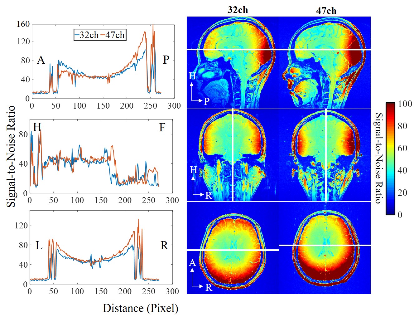
Gradient Echo (GRE) images (field of view (FOV) = 220 mm × 220 mm, acquisition matrix = 272 × 272, slice thickness = 1.8 mm, repetition time (TR) = 300 ms, echo time (TE) = 6.48 ms, bandwidth = 200 Hz/pixel, and flip angle (FA) = 30 degrees) were used to analyze SNR performance. The same sequence, while with the flip angle set to zero, was used to acquire the noise image for calculating the coil array noise correlation matrix [4] and the SNR maps. The SNR maps were calculated according to the noise covariance weighted root sum of squares (cov-rSoS) method [5].
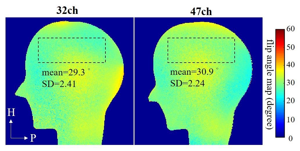
Two GRE sequences (FOV = 250 mm × 250 mm, acquisition matrix = 272 × 272, slice thickness = 1.8 mm, TR/TE = 1000/6.08 ms, pixel bandwidth = 360 Hz/pixel, echo trains length = 1) with FA = 30 degrees and 60 degrees respectively were used to calculate FA maps [6].
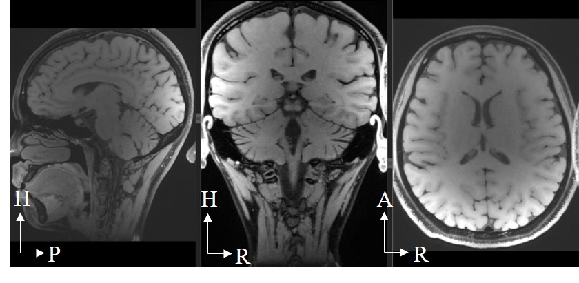
Modulated flip angle technique in refocused imaging with extended echo train (MATRIX) was used to acquire accelerated anatomical images on a volunteer (women, age 25-year-old, and weight 55 kg). The sequence parameters were set as follow: slices per slab = 256, slice thickness = 0.6 mm, FOV = 220 mm (readout direction) Х 192 mm (phase encoding direction), TR/TE=850/12.9 ms, Echo train length=46, Bandwidth=600Hz/Pixel.
RESULTS/DISCUSSION
The noise correlation matrix for each coil element of the PET/MR head coil is shown in Fig. 2. The mean value between two individual coil arrays is 0.08.The SNR maps and 1-D profiles acquired by two head coils are shown in Fig. 3. Compared with the commercial 32-channel head coil, the 47-channel PET/MR head coil shows better SNR performance at the periphery and comparable SNR performance in the central.
The flip angle maps were shown in fig. 4. ROI was considered as brain area. The mean and standard deviation values in selected ROIs of the two coils were comparable.
0.6 mm isotropic, full-brain, 7-fold accelerated anatomical images acquired by the 47-channel PETMR head coil array was shown in Fig. 5.
CONCLUSION
A quadrature birdcage/47Rx head coil array designed and built for a dedicated PET insert was presented and tested on a 3T MRI system. The coil performances were compared with a 32-channel commercial head coil, which was often used in brain and cerebrovascular examination in MRI. The coil performances of the PET/MR head coil show comparability with the commercial head coil, which leads to the highly possibility to achieve application in MRI to PET/MR studies.Acknowledgements
This work was supported in part by the Strategic Priority Research Program of the Chinese Academy of Sciences (Grant No. XDB25000000), Guangdong Province grants 2018B030333001, NSFC under Grant No. 81627901. Youth Innovation Promotion Association of CAS No. 2017415, and National Natural science foundation of China (Grant No.: 81671789)References
[1] Catana, Ciprian, et al. "PET/MRI for neurologic applications." Journal of nuclear medicine 53.12 (2012): 1916-1925.
[2] Sander, Christin Y., et al. "A 31‐channel MR brain array coil compatible with positron emission tomography." Magnetic resonance in medicine 73.6 (2015): 2363-2375.
[3] The Measure of Man and Woman: Human Factors in Design, by Alvin R. Tilley, Henry Dreyfuss Associates, 1993.
[4] X. Yan, Z. Cao, and X. Zhang, "Simulation verification of SNR and parallel imaging improvements by ICE-decoupled loop array in MRI," Appl Magn Reson, vol. 47, pp. 395-403, Feb. 2016.
[5] B. Keil and L. L. Wald, "Massively parallel MRI detector arrays," J Magn Reson Imaging, vol. 229, pp. 75-89, Apr. 2013.
[6] C. H. Cunningham, J. M. Paily and K. S. Nayak, “Saturated double-angle method for rapid B1+ mapping,” Magn. Reson. Med., vol. 55, no. 6, pp. 1326–1333, Jun. 2006.
Figures