4264
A dedicated 3-ch breast coil for Microwave Tomography at 3T1Innovation, Quality Electrodynamics, LLC, Mayfield Village, OH, United States, 2Thayer School of Engineering, Dartmouth College, Hanover, NH, United States
Synopsis
MR breast imaging has high sensitivity but not high specificity. Microwave Tomography (MT) provides complimentary permittivity information that may improve specificity. MT has poor spatial resolution. Combining MR and MT may address both spatial and specificity issues. Previous MT and MR work demonstrated the MT-MR combination potential. However, there is no dedicated MR coil available for MT-MR combination. The only available coils are the whole-body coil or a single-loop coil that have poor MR image quality. A dedicated 3-ch MRI coil is proposed here for superior MRI imaging quality which enables the next step MT-MR volunteer evaluation.
Introduction
MR breast imaging has high sensitivity but not specificity. Microwave Tomography (MT) measures breast permittivity that may be complimentary for improved specificity. However, MT spatial resolution is poor. Combining MR and MT appears to be a good candidate to address both. Previously, MT with MR imaging was demonstrated using a 16-monopole array positioned on a 15.2 cm circle [1]. The monopole array was immersed in a cylindrical tank fully filled with a glycerin:water mixture. A circular opening on the tank top cover allows breast access for MT imaging. The glycerin:water bath provides high attenuation (<-120dB) over the MT frequency range(~GHz) but almost no attenuation at the MR frequency (123.2MHz). The huge attenuation ensures the MT signals through the breast dominate while those travelling through the glycerin:water are suppressed below noise level. However, the monopole antenna array with the liquid tank setup is not MR coil friendly. The demonstration can only use either the whole-body-coil (WBC) or a single loop coil under the tank for MR imaging (Figure 1). A dedicated 3-ch MRI coil is proposed here for improved MRI imaging quality which enables the next step MT-MR volunteer evaluation.Methods
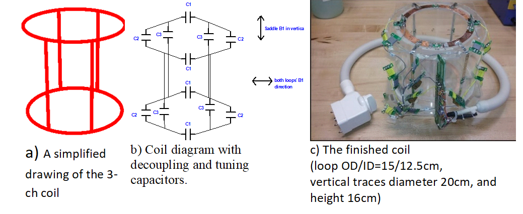
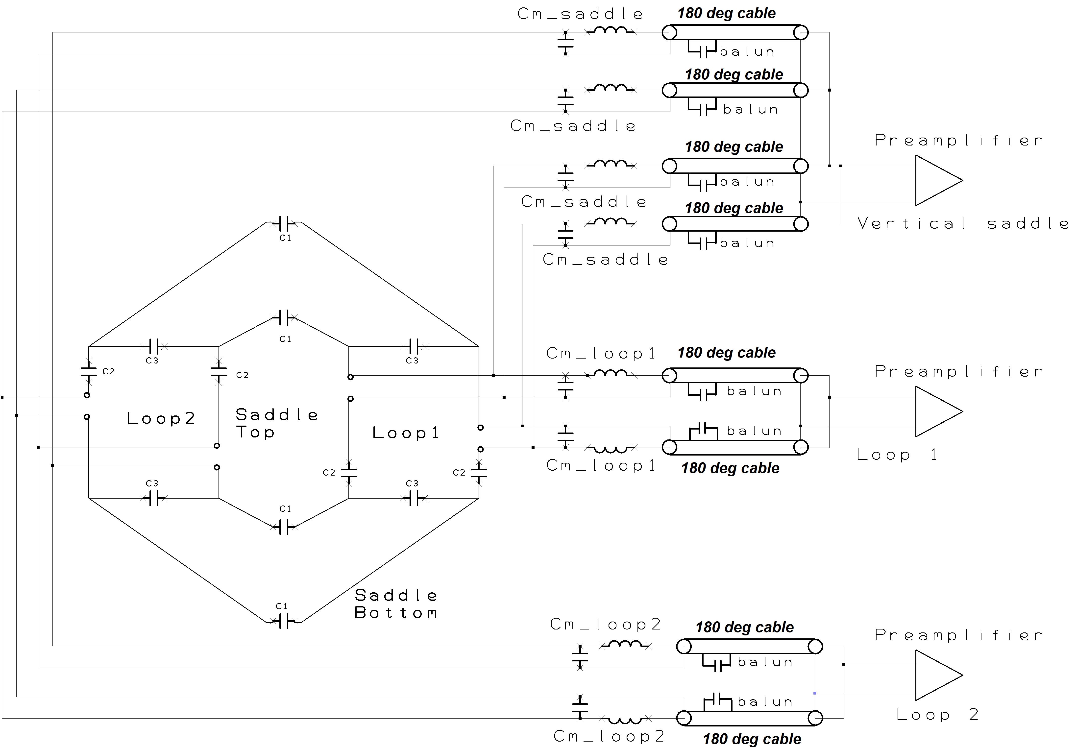
The high attenuation configuration requires that no other materials be present within the monopole-array-diameter-plus-4-cm circle. This is because other materials can scatter the direct monopole-monopole signals and cause unwanted multipath signals. Thus, the MRI coil must be completely outside the diameter+4cm circle. It must be integrated into either into the actual tank wall or positioned just outside of it. The tank wall thickness is roughly 0.63 ~ 1.27 cm. These requirements present two challenges for the MRI coil: very limited space and the imaging area is far from the coil (i.e. lower SNR). A two-loop with four vertical traces structure is presented here to address the challenges. Figure 2 shows the coil structure, its simplified circuit diagram and the finished coil photo. The structure has only one layer and can be built directly into the tank wall. The structure supports three resonant modes/channels, i.e., a two-loop saddle in the vertical direction and two loops in the horizontal direction. All three channels create a volume quadrature detection for high SNR within the imaging area. The two loop channels are coupled inductively because they face each other. All C1s and C3s are used to provide necessary capacitance for channel decoupling [2]. The two loops are geometrically decoupled from the vertical saddle. We empirically adjust C1s, C2s and C3s to ensure all channels resonate at the working frequency and having good decoupling between them. Phased arrays are widely used in multi-channel MR coils [3]. They not only provide additional low input impedance preamplifier decoupling but also stabilize the MRI coil signal from patient loading variations. Its use in this 3-ch coil is strongly desired. As aforementioned, C3 and C1 paths provide capacitive decoupling between the horizontal loops, i.e., decoupling current flows in Rx mode. Thus they cannot be used as channel matching/feeding points because the high impedances generated by the low input impedance preamplifier disables the decoupling currents. Therefore, the only places to feed all channels are the C2 paths. This means that the same four C2 paths are shared by all three channels, i.e. all channels use the same matching points. Figure 3 shows the matching diagram of all three channels using the same four feeding points. Each Cm resonates with its closest matching inductor for array coil high impedance. Each Cm and their inductors are connected to a 180-degree coaxial cable with an integrated solenoid balun. In addition, each Cm is connected to one of the four matching points in such a polarity so that the saddle channel forces a saddle current flow and the loop channels force loop current flows. Each Cm/inductor values are also chosen properly so that each preamplifier is presented with a 50 Ohm termination for optimal coil/preamplifier noise matching. Workbench tests show good channel matchings and isolations using this structure and matching scheme.Results
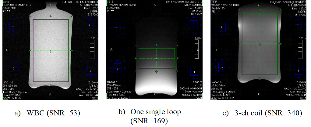
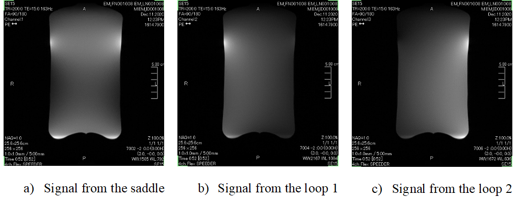
The coil was scanned in a Canon Galan 3T system with a cylindrical phantom (diameter=12cm and height=20cm, 75% glycerin/25% water). The same SE 15 sequence is used for all SNR comparison. Three cases are measured: the WBC only, a one-loop coil (14cm diameter), and the 3-ch coil. Figure 4 shows all three SNRs. The 3-ch SNR is 6.8 times of the WBC and 2 times of the single loop at the intended imaging area. In addition, the 3ch coil has much better uniformity than the one loop coil. Figure 5 shows each channel signal pattern of the 3-ch coil. As expected, distinctive signal patterns of saddle and loops are observed. It confirms that both the channel isolation and feeding schemes work as designed.Conclusion
A dedicated novel 3-ch MR phased array coil for MT imaging at 3T was constructed and tested. Compared to the WBC and a single-loop coil, the new coil has superior image quality. The future work will integrate the 3-ch coil into the water tank/monopole array for volunteer study.Acknowledgements
This work is supported by the National Institutes of Health PTE Federal Award No 1R01CA240760-01A1.References
1. Paul M. Meaney, et, al, Med. Phys. 40 (10), October 2013
2. Wang J., Proc. ISMRM 4:1434 (1996).
3. P.B. Roemer et al, Mag. Reson. in Med. 16, 192-225 (1990).
Figures
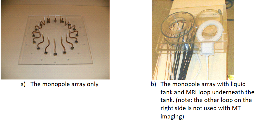
Figure 1. The monopole array, water tank and MRI coil setup [1]