4253
Real-Time B0 Correction in a MRI Guided Radiotherapy System1Biomedical Engineering, Washinton University in Saint Louis, Saint Louis, MO, United States, 2Radiation Oncology, Washinton University in Saint Louis, Saint Louis, MO, United States, 3Radiology, Washinton University in Saint Louis, Saint Louis, MO, United States
Synopsis
MRI linear accelerator hybrid systems use balanced steady state free precession sequences (bSSFP) during radiotherapy due to the sequence’s high signal to noise ratio and rapid acquisition times. However, bSSFP sequences are highly sensitive to off-resonance effects.1 As a result, the position and velocity of the radiotherapy gantry can cause imaging artifacts that can impact tumor tracking and cause fluctuations in the main magnetic field that can result in radiotherapy/MRI isocenter misalignments. Sequence parameters were adjusted during the sequence run time to reduce these issues by integrating a navigator into the bSSFP sequence and measuring B0 variations in real-time.
Purpose
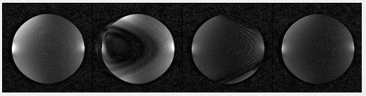
Gantry rotation in MRI-guided radiotherapy (MR-IGRT) systems results in image artifacts and spatial shifts due to electromagnetic interference (EMI) between the MRI and linear accelerator (linac) subsystems (Fig. 1).2 Additionally, B0 in MR-IGRT systems displays gantry angle position dependence due to the metal (e.g., ferromagnetic) components located in the gantry.3–5 Changes in B0 can result in: 1) imaging artifacts that can impact tumor tracking; and 2) isocenter shifts that can cause misalignments between the radiotherapy and MRI subsystems. The purpose of this study was to measure and correct the B0 field variations in real time associated with the gantry position in a balanced steady state free precession (bSSFP) sequence.Methods
A hard pulse navigator (FA:70, dwell time = 8 µs, complex points = 64) was added to a 2D Cartesian bSSFP sequence (TE/TR: 1.7/3.4, FA: 70°, rBW: 558 Hz/pixel, single average) preceding each image acquisition on a ViewRay 0.35 T MRI-Linac. ViewRay uses the Siemens IDEA/ICE programming environment (VB19) and electronics. Measurements were performed using a spherical 24 cm DSV phantom doped with 5 mM NiSO4 (T1/T2: 330/260 ms) using phased array torso coils designed for use in the MR-IGRT system. Phase data from the first navigator was used as a reference, and the central frequency offset was determined using phase data from each subsequent navigator. The frequency offset was then passed back to the sequence from the image calculation computer as a real time feedback object and used to adjust the resonant frequency for the bSSFP image pulses and receiver. B0 fluctuations as a result of EMI were measured by allowing the gantry to rotate uninterrupted counterclockwise from 30° to 33°. In addition, the B0 variations due to the stationary gantry from 30° to 33° in 15° increments Shimming for both experiments was performed at gantry angle 30° prior to gantry rotation. The calculated central frequency offsets from the bSSFP navigators were compared against shifts in the peak frequency from a pair of FID sequences (rBW = 4Hz/point for EMI induced B0 offsets and rBW=1Hz/point for stationary gantry related B0 offsets). Linear interpolation was used to align the time bases of the navigator and of the FID data for comparison.Results and Discussion
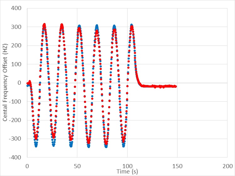
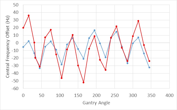
Central frequency shifts calculated using the inserted bSSFP navigators showed similar results as the reference FID data both while the gantry was rotating (RMSE = 20.9 Hz, Fig. 2) and while the gantry was stationary (RMSE = 15.5 Hz, Fig. 3). The EMI from gantry rotation resulted in B0 offsets about 10 times larger than the B0 shifts due to the stationary gantry position. Both sets of B0 offsets displayed sinusoidal behavior with a period of 60°. This behavior corresponds to the six 227 kg mu-metal shield buckets on the MRI-Linac that are spaced 60° apart and house accelerator components (Fig. 4). In 2020, ViewRay offered a gantry angle dependent B0 correction that is designed for their Step and Shoot radiation therapy delivery in which the gantry is stationary during radiation delivery. Currently, faster radiation delivery techniques are not possible for MR-IGRT systems due to gantry angle and time-dependent EMI between the linac and MRI subsystems. The B0 navigator is being developed to permit real-time B0 correction for arc therapy in which radiation could be delivered during gantry rotation. Currently, the method is restricted to Cartesian acquisitions. However, the navigator can be adapted to radial acquisitions. ViewRay currently offers 4 frames/s Cartesian and 8 frames/s radial bSSFP (TrueFISP) sequences for real-time target tracking and beam gating during radiotherapy.Conclusion
Navigators inserted into MR-IGRT sequences offer a promising way to rapidly account for gantry angle related variations in B0 and to compensate by adjusting sequence parameters in real time.Acknowledgements
No acknowledgement found.References
1. Bieri O, Scheffler K. Fundamentals of balanced steady state free precession MRI. J Magn Reson Imaging. 2013;38(1):2-11. doi:10.1002/jmri.24163
2. Gach HM, Curcuru AN, Wittland EJ, et al. MRI quality control for low-field MR-IGRT systems: Lessons learned. J Appl Clin Med Phys. 2019;20(10):53-66. doi:10.1002/acm2.12713
3. Gach HM, Curcuru AN, Mutic S, Kim T. B0 field homogeneity recommendations, specifications, and measurement units for MRI in radiation therapy. Med Phys. 2020. doi:10.1002/mp.14306
4. Kim T, Gu B, Maraghechi B, et al. Characterizing MR Imaging isocenter variation in MRgRT. Biomed Phys Eng Express. 2020;6(3). doi:10.1088/2057-1976/ab7bc6
5. Latifi K, Moros EG, Zhang G, Harrison L, Feygelman V. A Method to Determine the Coincidence of MRI-Guided Linac Radiation and Magnetic Isocenters. Technol Cancer Res Treat. 2019;18:1-6. doi:10.1177/1533033819877986
Figures