4217
A multi-spectral imaging template of hip arthroplasty showing distribution of 3T vs. 1.5T artifacts in the acetabulum of varying implants1Radiology, Medical College of Wisconsin, Milwaukee, WI, United States
Synopsis
An average proton density weighted template of the hip with arthroplasty was developed, and multi-spectral images from patients acquired at both 1.5T and 3.0T were registered to it. As a proof-of-concept, maps of residual metal artifact were transformed into the template space and, for different implant compositions, probability maps of residual artifact were generated. Ceramic implants exhibit minimal cross-field artifact differences, while metal-on-metal implants show more profound differences and metal-on-poly implants exhibit more moderate differences. This template and registration software lays the foundation for future quantitative analysis of cross-session and cross-subject imaging of hip arthroplasty.
Introduction
The use of standardized “template” spaces has yielded significant advances in cross-exam and cross-patient comparisons in research imaging of the brain [1], prostate [2], and hip [3] among other anatomy. Herein we develop such a template for the acetabular component of the hip with arthroplasty in proton density weighted multi-spectral MRI. Due to the articulation of the hip, template space for the acetabular and femoral components of the arthroplasty are best considered separately. With adverse tissue reaction more predominantly found around the acetabular component, the acetabular component is considered in this work. With a template space defined, a demonstration of field-dependent artifact extent is presented as a function of implant composition.Methods
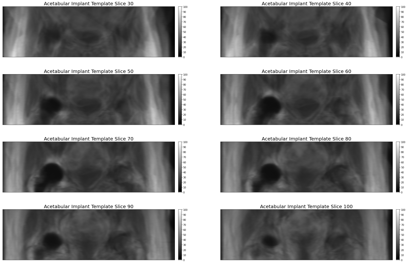
As part of an IRB approved study, patients who received 1.5T imaging of hip arthroplasty were called back for 3.0T imaging under informed consent. Ten patients were imaged, including six with metal-on-poly, two with metal-on-metal, and two with ceramic implant designs. Proton density (PD) weighted images were acquired at 1.5T (MAVRIC-SL, TR 2200 ms, TE 6.5 ms, 4 mm slice thickness, 24 slices, 40 cm field of view, 384x256 matrix, fast recovery) and 3.0T (MAVRIC-SL, TR 1825 ms, TE 6.5 ms, 4 mm slice thickness, 32 slices, 40 cm field of view, 384x256 matrix, fast recovery). On each image, the region of artifact around the implant was manually traced using the OHIF [4] viewer of XNAT [5], and tracings were exported as DICOM RTSTRUCT files.A 1.5T image of a subject with a ceramic implant and minimal artifact was selected as a base image for template generation. All images were resampled with linear interpolation to yield isotropic 0.73 mm resolution. For each subject, the implant volume was rendered by fitting radial basis functions [6] to the edge points defined in the RTSTRUCT. A center of mass registration between the participant’s 1.5T implant artifact mask and the template image artifact mask was performed for rough alignment, and applied to both the artifact mask and PD image which was scaled into a 16 bit grayscale intensity range. The implant artifact mask was then cut at its center of mass with the proximal component preserved and dilated with a 30 mm binary dilation filter to yield a neighborhood in the acetabular region for image registration evaluation using the Simple Insight Toolkit [7]. A mutual information cost function (200 bins) was evaluated in the overlapping acetabular neighborhoods of the template and participant images on the PD images, and a gradient decent optimizer was applied. Registration proceeded in a multi-resolution process with two-fold under sampling and a 9.4 mm FWHM Gaussian smoothing followed with a second step at template resolution with a 4.7 mm FWHM Gaussian smoothing. Once 1.5T images were registered to the template space, an average template was generated, shown in Figure 1. Using the same algorithm, all 1.5T images were then registered to the average template and 3T images were registered to the template-space 1.5T images for each subject.
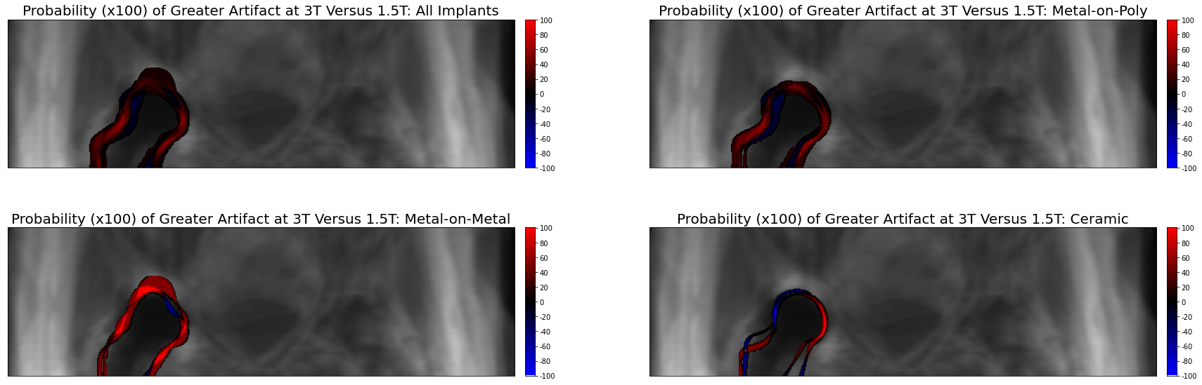
Resulting transforms were applied to each implant artifact mask to yield template-space maps of image artifact. The percentage of participants which exhibited artifact at each spatial location in the template space were computed across all implants and across each implant type. Figure 2 shows these artifact probability maps.
Results
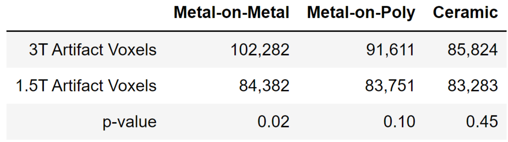
Figure 1 shows the template space and Figure 2 shows the spatial distribution of residual metal artifact in multi-spectral images across all implants and each class of implant. Figure 3 includes a table of the mean artifact, quantified in number of voxels in the region of the acetabulum, for each implant type as well as the p-value for a t-test comparing artifact volume across field strengths.Discussion
This work introduces the use of a template space for quantitative imaging in the acetabular region of hip arthroplasty. As a proof of concept, this work confirms that the region of residual metal artifact in the acetabulum around hip arthroplasty is dependent upon field strength and implant composition. By addressing the challenge of registration of hip images in the presence of significant patient positioning differences, this lays the foundation for further quantitative studies of cross-visit and cross-patient multi-spectral imaging data.Conclusion
A “standard space” template of the 1.5T multi-spectral imaging proton density weighted hip with arthroplasty is introduced. Registration of patients, each imaged at 1.5T and 3.0T, to the template enables the direct comparison of residual metal artifact for each patient across field strengths. Ceramic implants yield negligibly different artifact at higher field, while metal-on-metal implants yield maximal artifact differences and metal-on-poly implants present moderately increased artifacts. This work demonstrates a first step to quantifying field-dependent diagnostic quality differences when imaging hip arthroplasty devices of different compositions.Acknowledgements
No acknowledgement found.References
[1] Collins, D.L., Neelin, P., Peters, T.M., Evans, A.C., 1994. Automatic 3-D intersubject registration of MR volumetric data in standardized Talairach space. J. Comput. Assist. Tomogr. 18 (2), 192–205.
[2] McGarry, S. et al. The Medical College of Wisconsin 39 (MCW39): A Magnetic Resonance Image Template of the Prostate to Facilitate Group Analysis. Proc. ISMRM 2018: 4499.
[3] A. Virzì et al., "A new method based on template registration and deformable models for pelvic bones semi-automatic segmentation in pediatric MRI," 2017 IEEE 14th International Symposium on Biomedical Imaging (ISBI 2017), Melbourne, VIC, 2017, pp. 323-326.
[4] Urban, T. et al. LesionTracker: Extensible Open-Source Zero-Footprint Web Viewer for Cancer Imaging Research and Clinical Trials. Cancer Research, 2017 (77) (21) e119-e122.
[5] Marcus, Daniel S., et al. "The extensible neuroimaging archive toolkit." Neuroinformatics 5.1 (2007): 11-33.
[6] Buhmann, Martin D. "Radial basis functions." Acta numerica 9 (2000): 1-38.
[7] B. C. Lowekamp, D. T. Chen, L. Ibáñez, D. Blezek, “The Design of SimpleITK”, Front. Neuroinform., 7:45. doi: 10.3389/fninf.2013.00045, 2013.
Figures