4186
T2*-Weighted Imaging Using Gradient-Echo BURST Combined with EPI and Spiral Readout Trajectories1GE Healthcare, Munich, Germany, 2GE Healthcare, Waukesha, WI, United States
Synopsis
BURST MRI is a way of exciting magnetisation sequentially and storing it in k-space. In this work, gradient-echo BURST MRI is combined with the sampling efficient Echo-Planar Imaging (EPI) and Spiral gradient trajectories. High quality T2*-weighted images were acquired both in phantom and in vivo, demonstrating the potential of this combination for reducing B0 related artefacts.
Introduction
BURST MRI is a way of exciting magnetisation sequentially and storing it in k-space. Either gradient or spin echoes are generated at a later time point during the pulse sequence, and spatial information is encoded through magnetic field gradients [1]. Despite some advantages in terms of sampling efficiency and acoustic noise, BURST MRI has never found wide-spread application in the MRI community [2], including functional MRI (fMRI)[3].BOLD contrast is typically encoded via T2* sensitive sequences in fMRI. The most common encoding scheme is single-shot Echo-Planar Imaging (EPI) with TE≈30ms at B0=3T. The main advantage of EPI is rapid imaging in a single-shot per single slice. The main disadvantage are artefacts, especially geometric distortions and signal dropout because the long EPI trains are sensitive to B0 inhomogeneities. Another highly encoding efficient, but less popular readout trajectory for fMRI are single-shot Spirals [4]. Again, the long Spiral trajectory is sensitive to B0 inhomogeneities, resulting in blurred images.
In this work, BURST MRI is combined with the sampling efficient Echo-Planar Imaging (EPI) and Spiral gradient trajectories. BURST enables splitting the long single-shot trajectories into multiple segments acquired inside the same pulse-and-acquire block, thereby reducing artefacts stemming from B0 inhomogeneities.
Methods
The proposed BURST sequence as shown in Fig. 1 starts with a train of four small-tip angle, slice-selective RF pulses. After each RF pulse, the excited magnetisation is stored in outer k-space. Two variants of storing this magnetisation were implemented: one uses gradients in xy-direction (in-plane), moving the stored magnetisation sufficiently (~1.5 times k-max) far out that it does not get refocused accidentally during the other echoes (Fig. 1 top and middle row). The other implementation uses gradients in z-direction (through plane) for storing magnetisation along the slice-selection direction (Fig. 1 bottom row).The readout trajectory following this train of slice-selective RF pulses are split into four segments. The first segment uses the magnetisation excited by the first sub RF pulse, the second segment the magnetisation excited by the second sub RF pulse and so on. To achieve this, the zeroth-order gradient moment is balanced from centre of the sub-RF pulse to the centre of k-space of the corresponding readout segment.
A key advantage of splitting the long readout trajectory into four segments is that each sub-trajectory is only a quarter as long as the original single-shot trajectory. This reduces the corresponding B0-related artefacts accordingly, while not increasing scan time as much as when segmenting the acquisition into different excitations.
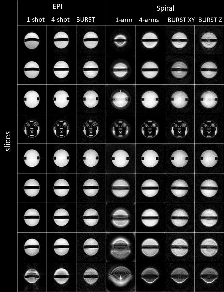
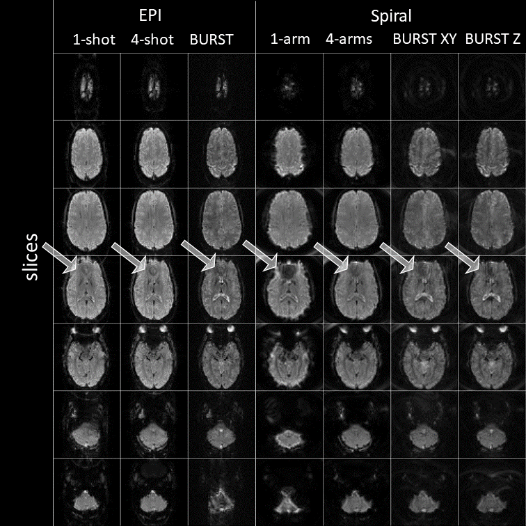
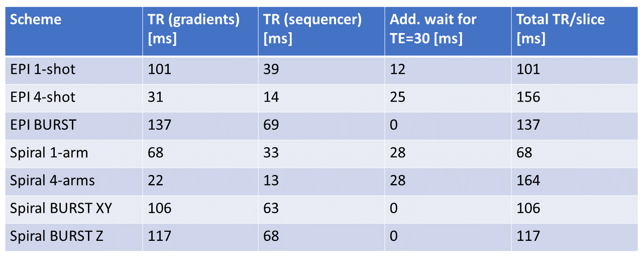
The proposed BURST EPI and Spiral schemes were implemented in a flexible sequence (“fidall PSD”), where RF waveforms, gradient trajectories and other modulations are read in from file. Reconstruction was implemented in Matlab (The MathWorks, Natick, MA, USA) running automatically on the MRI scanner. Experiments were performed on a whole-body 3T MRI scanner (MR750w, GE Healthcare, Milwaukee, WI, USA) using a multi-channel head receive coil. To facilitate a direct and fair comparison, the different encoding schemes were all implemented in the same framework using the same acquisition parameters: FOV=(19.2cm)2, matrix size=64x64, slice thickness=3mm, slice spacing=17mm, #slices=7 (brain) and 9 (phantom). The encoding schemes are single-shot EPI (trajectory duration=32.9ms), 4-shot EPI (8.6ms), BURST EPI (with four segments, each 8.6ms), single-arm (=shot) Spiral (26.7ms), 4-arm Spiral (6.7ms), BURST Spiral storing magnetisation along z or xy (also with four segments, each 6.7ms). The repetition times per slice are listed in Table 1 for all different encoding schemes. The EPI scans included a calibration scan with nulled phase blips.
Results and Discussion
BURST EPI and Spiral imaging is possible, yielding high quality images (phantom in Fig. 2; brain in Fig. 3). The B0 artefact behaviour is varying among the different encoding schemes and can be best observed in outer slices of the phantom (Fig. 2) and more importantly in the sinus area of the brain (Fig. 3). The phantom represents an extreme case due to the cylindrical geometry of the phantom, hence extraordinary large B0 variations. Single-shot EPI shows geometric distortions, while single-arm Spiral shows blurring. This is greatly reduced in the four-shot acquisitions as well in the BURST acquisition using four segments.The EPI data was corrected with a calibration scan, which reduced artefacts such as ghosting. Spiral image quality could be improved via B0 correction in the reconstruction, requiring accurate knowledge of B0 maps, which is somewhat challenging in practice.
The goal of this work was to introduce the BURST concept to T2*-weighted imaging. Thus, no advanced methods such as parallel imaging were applied. However, this would improve EPI image quality further, applying equally well to BURST EPI.
Standard EPI and Spiral MRI used flip angles of 90°. For BURST, this had to be reduced because each flip depletes the same Mz pool. Here, each sub-RF pulse excited magnetisation with 15°, hence reducing SNR accordingly. However, BURST can easily be combined with a variable flip angle scheme.
In most cases, the effective TR was restricted by gradient duty cycle (Table 1). BURST generally increases the effective TR, but is shorter as compared to multi-shot acquisitions. The exact relationship depends heavily on hardware and trajectories.
Conclusion
Combining EPI and Spiral T2*-weighted imaging with BURST reduces artefacts induced by B0 inhomogeneities.Acknowledgements
No acknowledgement found.References
[1] Burst imaging. Hennig J, Hodapp M. MAGMA. 1993; 1:39-48.
[2] Burst imaging—Can it ever be useful in the clinic? Doran SJ, Bourgeois ME, Leach MO. Concepts Magn Reson Part A. 2005; 26A(1):11-34.
[3] Functional burst imaging. Jakob PM, Schlaug G, Griswold M, Lovblad KO, Thomas R, Ives JR, Matheson JK, Edelman RR. Magn Reson Med. 1998 Oct;40(4):614-21.
[4] Spiral imaging in fMRI. Glover GH. Neuroimage. 2012 Aug 15;62(2):706-12. doi: 10.1016/j.neuroimage.2011.10.039.
Figures