4044
Educational Tabletop MRI system using the Open-Source Console for Real-time Acquisition (OCRA)1Otto-von-Guericke University, Magdeburg, Germany, 2Research Campus STIMULATE, Magdeburg, Germany, 3Q Bio Inc, San Carlos, CA, United States
Synopsis
A Tabletop MRI system was developed that merges the Marinos Center Tabletop and OCRA projects, and is improved in many aspects compared to the original system. The proposed system includes a fully functional MRI console with a customizable GUI and microcontroller server. The hardware was extended with an optimized magnet design with passive shimming, active TR switches with reverse bias and RFPA noise blanking, and a low cost and fast response 4 channel gradient amplifier. It can be used for educational purposes and student courses in medical engineering.
Introduction
Using real-world Tabletop MRI systems as tools in MRI education has been shown to be very effective [1]. While the Martinos Center has made its hardware designs available as open-source, their system did not include a console. Inspired by that design, a complete Tabletop MRI system, which integrates the Open-Source Console for Real-time Acquisition (OCRA) project [2], was developed [3]. Almost all components were redesigned to extend the functional specifications and further improve the manufacturability to reduce the costs of the system.Methods
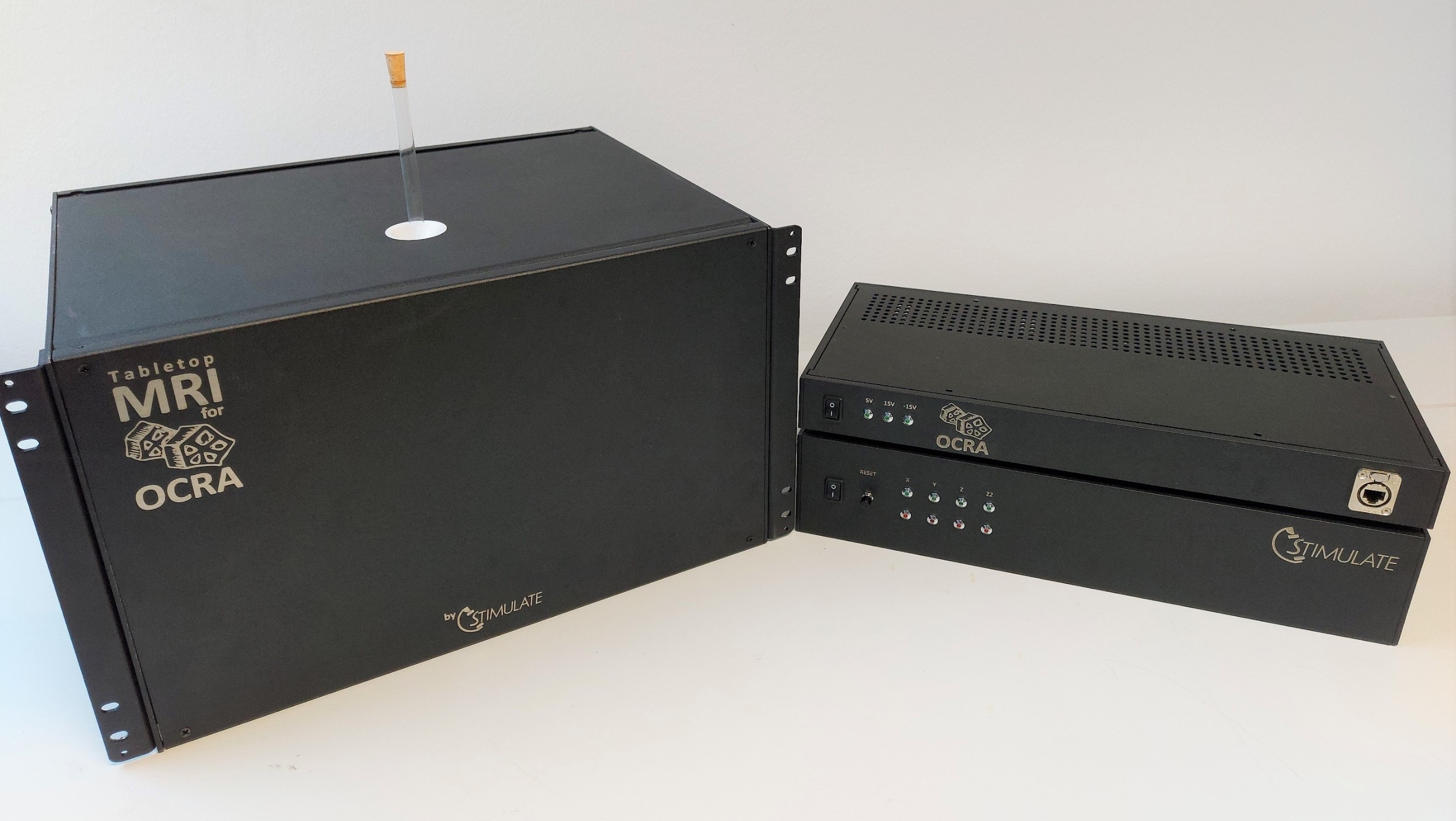
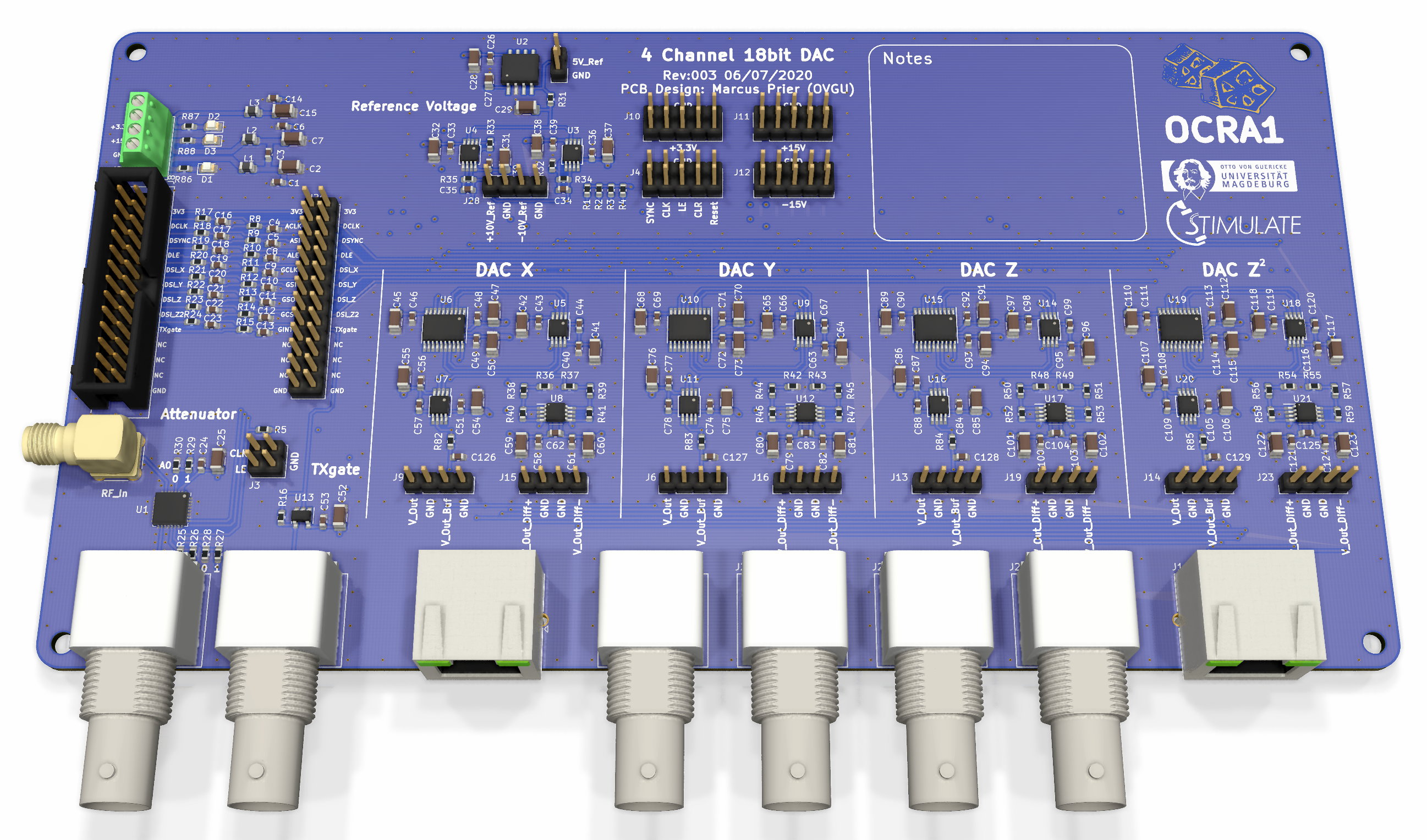
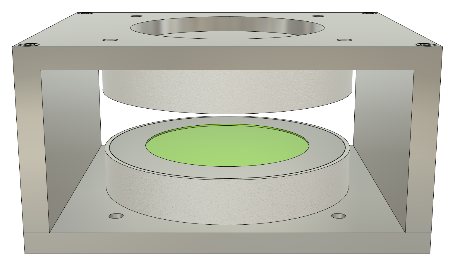
The OCRA MRI console is built around the STEMLab board, which features a Xilinx Zynq 7020 SOC. The SOC serves as real-time controller and interprets control commands, sent by a custom GUI on a host computer (Fig. 3). The STEMLab can output radio frequency (RF) pulses up to about 62MHz and samples the received MR signal with 122.8MSamples/s. SPI bus lines are generated on its GPIO pins to control lower frequency peripheral hardware [4]. We extended the STEMLab board by the peripheral OCRA1 board (Fig. 2), which generates all the low-frequency waveforms using the serial bus. It contains four 18bit DACs to generate analogue gradient waveforms with up to 200kSamples/s and also DC shim offsets for X, Y, Z and Z². Furthermore, a digitally controlled 7-bit RF attenuator enables RF pulse amplitude scaling [5].We also further optimized the MRI magnet in field homogeneity and manufacturing cost. Through numerical simulations of the magnetic flux density in COMSOL the optimal geometry was determined. A major feature is the addition of an integrated (milled) one-step pole shoe modulation (Fig. 4) for passive shimming, like seen in other MRI permanent magnets yokes [7]. The whole magnet assembly is installed in a CNC milled standard 19-inch aluminium rack enclosure for RF noise shielding and easy laboratory integration (Fig. 1).
The RF chain was augmented with an active T/R switch, that also features a reverse bias system for faster TX to RX switching, allowing much shorter echo times than the original system. It’s also extended with an additional TX “blanking switch” to provide fast RFPA noise blanking capabilities. The preamplifiers were upgraded to a low noise-figure model from Mini Circuits, providing good SNR at very low cost.
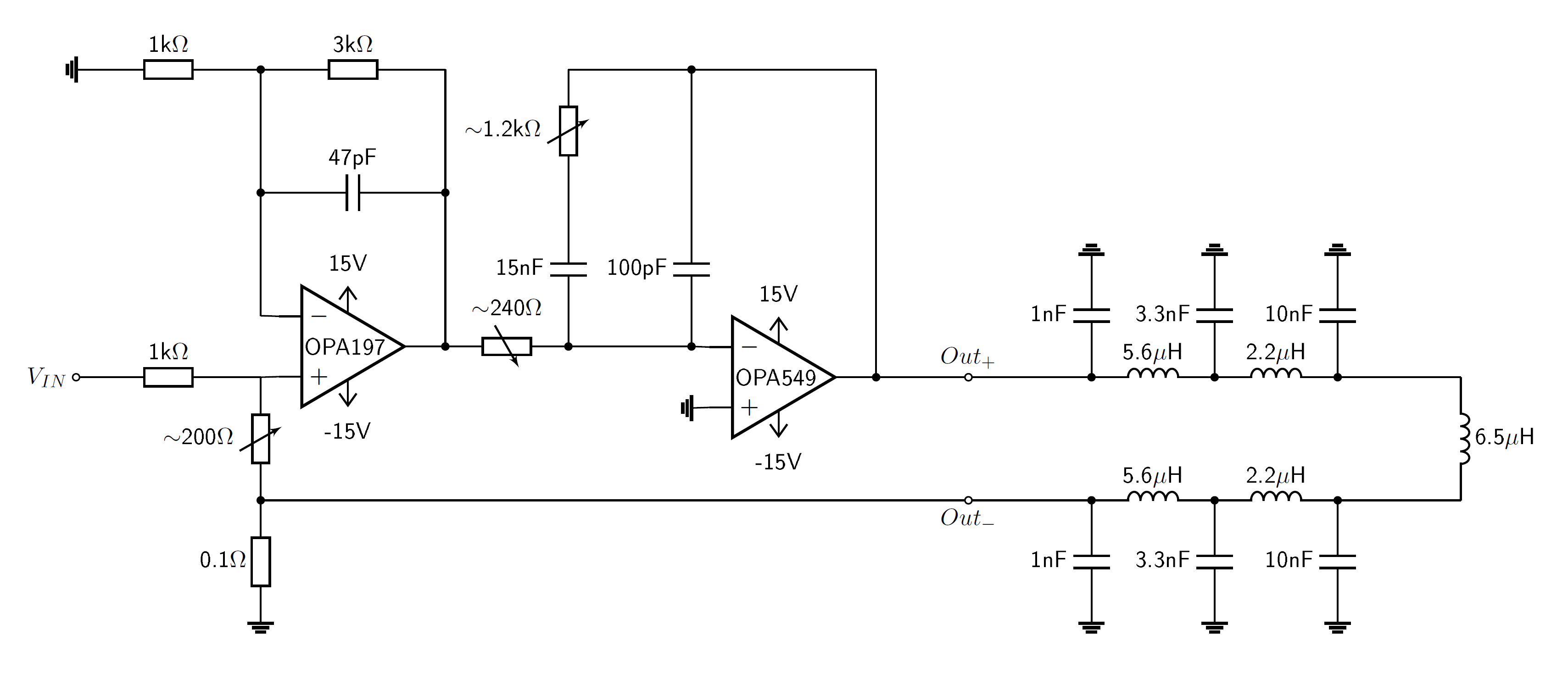
A miniaturized 4-channel gradient amplifier was developed. Significant cost reduction was accomplished by using only a single OPA549 power op-amp per channel as output stage (Fig. 5), as this can generate sufficient current for all pulse sequences. To mitigate gain-bandwidth product limitations and augment the DC stability of the amplifier, a J-FET OPA197 was chosen as main summation amplifier. In addition, the GPA includes a settable over-current and over-temperature protection, error state latching with LED status display and a channel reset option.
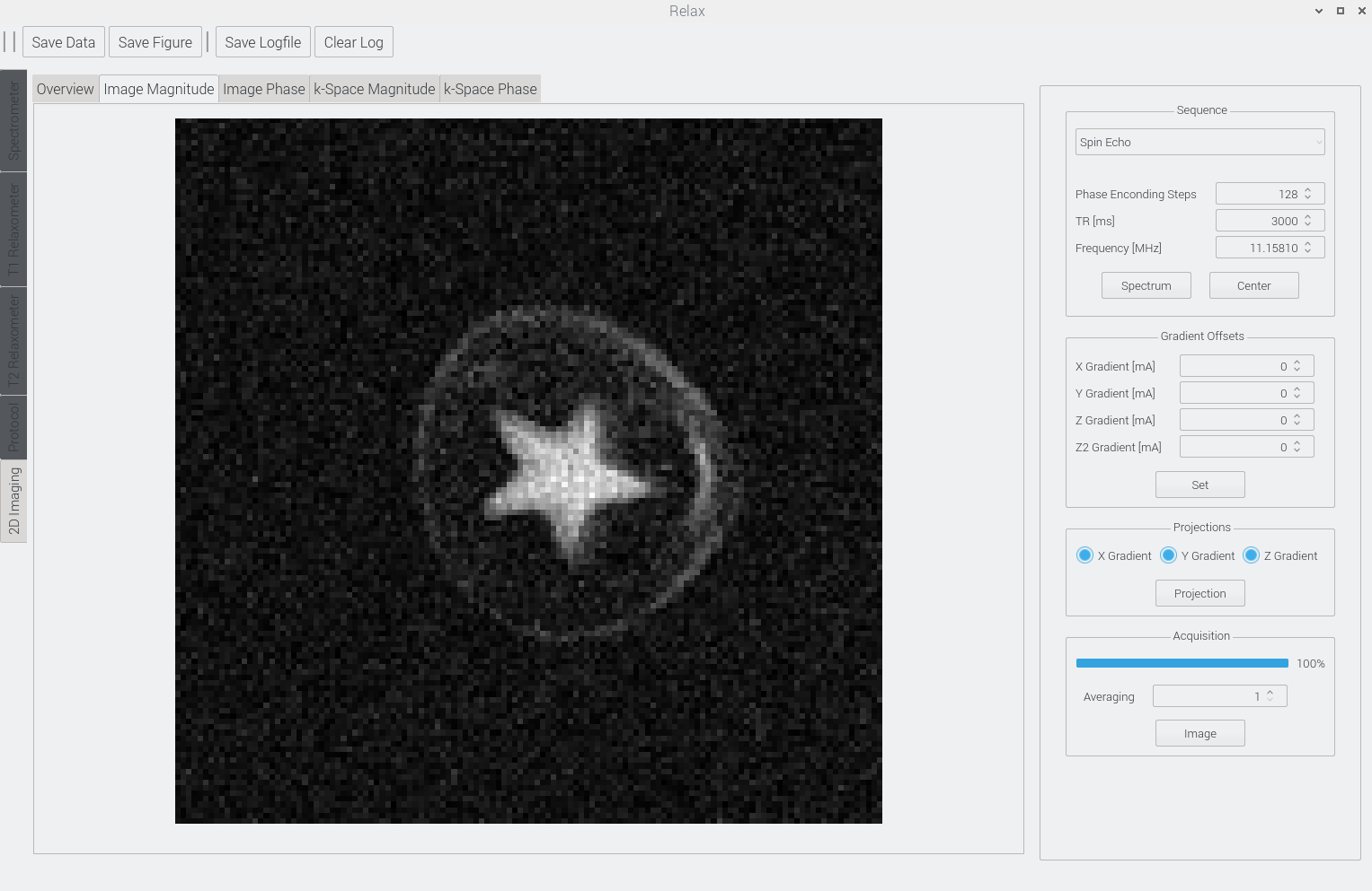
The software, that controls the hardware consists of the server on the STEMLab board and the graphical user interface (GUI) on a host computer. RF pulses and digital control signals are predefined by commands with adjustable durations, which are collected in pulse sequences. Sequences are transferred from the host computer to the server as a byte stream via a transmission control protocol (TCP). Gradient waveforms are generated on the server, dependent on the measurement requested. Redesigns to the existing OCRA GUI were made to improve the acquisition of NMR spectra and MR imaging, but also to includeT1 and T2 relaxometry as a new feature. Missing measuring tools to calibrate Larmor frequency or transmit power were implemented. Measurement results like images are visualised in tabs and metrics, like SNR or FWHH values, provide direct feedback on the signal quality (Fig. 3).
Results
The developed OCRA1 PCB extends the STEMLab board into a basic MRI console for NMR spectroscopy, relaxometry, and MR-imaging. The console provides RF pulse generation, active TR switching, a fully digital NMR receiver, and gradient pulse and offset waveform generation for X, Y, Z, and Z².The simulated magnet inhomogeneity was substantially reduced to 11ppm in 15mm possible DSV by the integrated passive shimming (Fig. 4). With active shimming the measured real inhomogeneity by FID FWHH is about 13ppm at 11.26MHz (0.265T) in a 10mm water sample. This allows MR imaging as shown in Figure 3. It shows that a simple integrated pole shoe modulation is a good compromise to archive imaging grade field homogeneity while still avoiding the labour cost of manual iron shimming.
The new simplified gradient power amplifier can handle ±10A peak and about ±1A steady-state current on each channel and provides a flat frequency response up to 38kHz, when loaded with the gradient coil and gradient filters.
The software was extended and new measuring features were added.
Discussion
A complete Tabletop MRI system was developed that merges the MC Tabletop and OCRA projects. The proposed system includes a basic MRI console with a customizable GUI and microcontroller server. The hardware was extended with features like an optimized magnet design, active TR switches, and a low cost and fast response 4 channel gradient amplifier. The OCRA Tabletop MRI system has already been successfully deployed at the Otto-von-Guericke University Magdeburg for educational purposes and student projects in medical engineering. Through the didactic application of the system, further improvements can be incorporated continuously.Acknowledgements
Parts of this projects are financed from the joint project "F&E RF-System für Neonatale MR-Tomographie" (FKZ: ZS/2018/04/91668) from the European Regional Development Fund.
The Tabletop system was developed and build in the ego.-Inkubator-"FLEXtronic-Gründungslabor für flexible Elektronik" IK 05/2015 from the European Regional Development Fund at the Research Campus STIMULATE.
Special thanks to Larry Wald and his team for making the original Tabletop MRI system construction plans available.
References
[1] Clarissa Zimmerman Cooley et al. “Design and implementation of a low-cost, tabletop MRI scanner for education and research prototyping”. In: Journal of Magnetic Resonance 310 (2020), page 106625. DOI: https://doi.org/10.1016/j.jmr. 2019.106625.
[2] Suma Anand et.al. “A low-cost (<$500 USD) FPGA-based console capable of real-time control“ ISMRM2018.0948
[3] https://zeugmatographix.org/ocra/2020/11/05/the-ocra-project-in-magdeburg-germany/ [4] https://openmri.github.io/ocra/
[5] https://zeugmatographix.org/ocra/2020/11/27/ocra1-spi-controlled-4-channel-18bit-dac-and-rf-attenutator/
[6] https://tabletop.martinos.org/index.php/Hardware:Magnet
[7] Yi Li et al. “Shape optimization of ferromagnetic pole of a superconducting MRI magnet with niching generic algorithm”. In: 2015 IEEE ASEMD (2015), DOI: 10.1109/ASEMD.2015.7453641
Figures