4042
The role of non-random magnet rotations on main field homogeneity of permanent magnet assemblies1C.J. Gorter Center for High Field MRI, Leiden University Medical Center, Leiden, Netherlands
Synopsis
Arrays of permanent magnets are an attractive approach to designing magnets for low field MRI systems as they are affordable, easy to handle and offer great flexibility in magnet designs. However, translating designs from simulations to realised systems is challenging. The difference between the two is often attributed to imperfections in the individual magnets that make up the permanent magnet array. Here we show that non-random errors in the magnet rotations due to imperfect magnet holders can be the dominant cause of this discrepancy and if the imperfections are known they can easily be corrected for during manufacturing.
Introduction
Halbach arrays have gained increasing attention in recent years as a method for designing low-cost, lightweight magnets suitable for MRI. The theoretical ‘ideal’ cylindrical dipolar Halbach array, consisting of a continuous magnetization that rotates twice over around the cylindrical circumference and that is infinitely long produces a perfectly homogeneous magnetic field oriented across the bore of the cylinder[1]. In practice, however, the homogeneity of these magnet systems is degraded. In the design stage two distinct sources of inhomogeneities arise; the finite length of the magnet[2] and using discrete magnets rather than continuous magnetization distributions[3]. Various methods to mitigate both of these suggested in literature [4-6]. During manufacturing two additional causes of inhomogeneity are often suggested to be important, i.e. the remanence field and the magnetization direction of the individual magnets have a certain variance which causes degradation of the homogeneity compared to simulations[7]. However, in this work we show that in a practical situation non-random rotations of the magnets inside the magnet holders can actually be the dominant cause of magnetic field perturbations when constructing Halbach arrays.Method
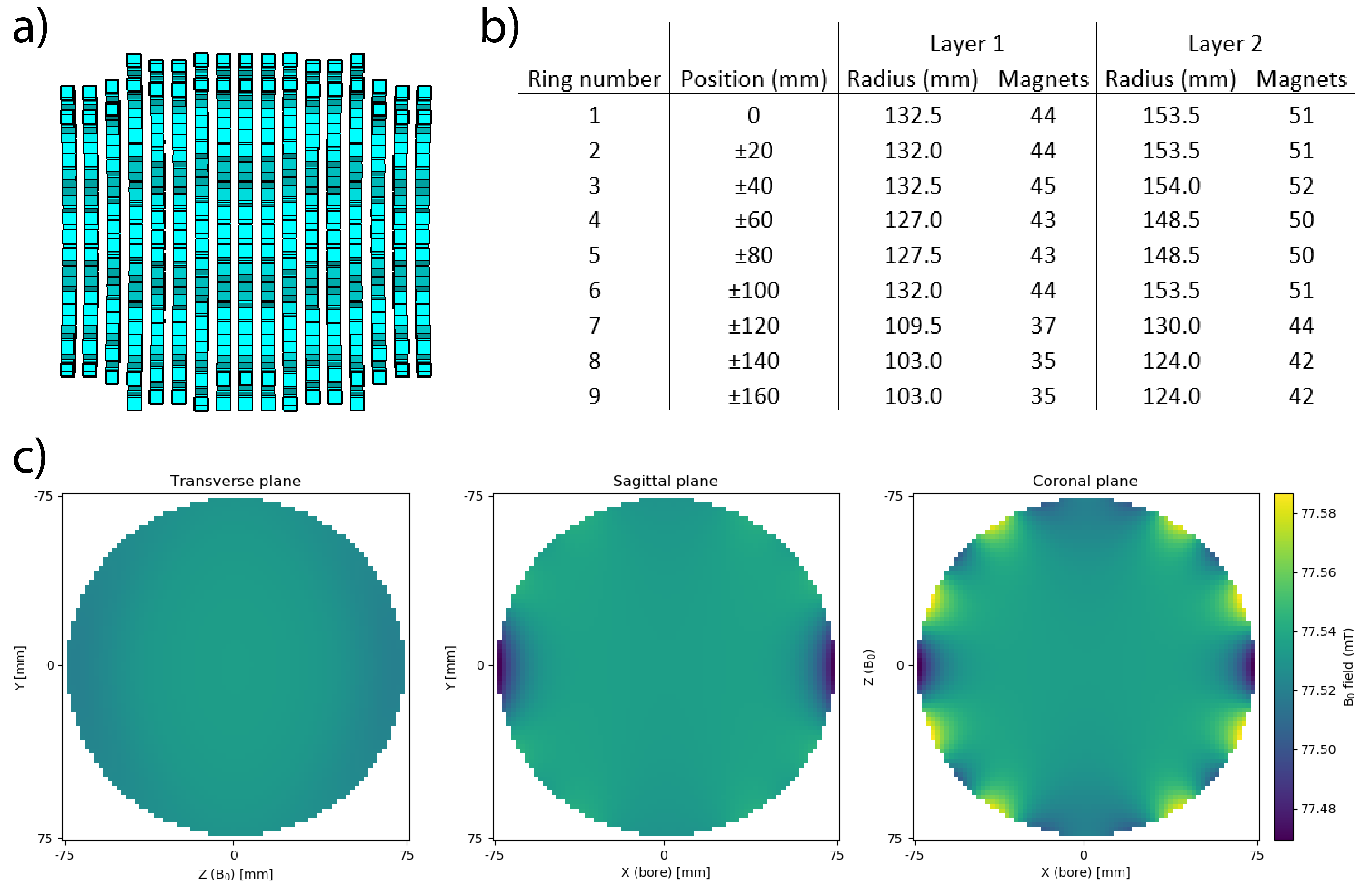
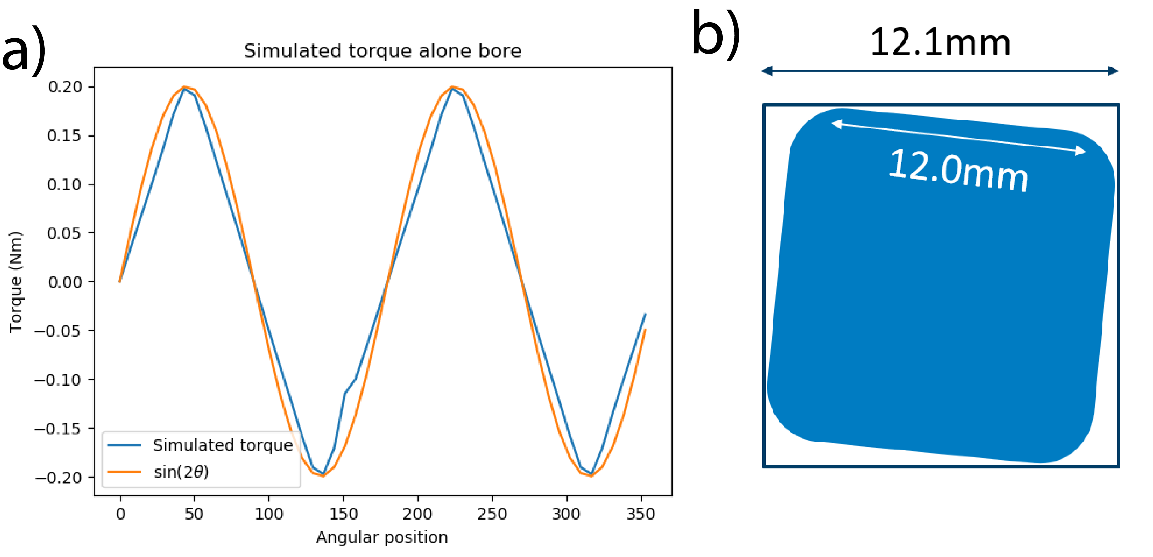
A Halbach array was designed for wrist imaging with an open bore of 18 cm and the homogeneity optimized over a 15 cm DSV at the center of the magnet. The magnet consist of 17 rings spaced 20 mm apart where each rings contains two layers of 12x12x12 mm3 N48 NdFeB magnets. The diameter of the rings was varied to optimized the homogeneity over the previously mentioned 15 cm DSV. Mirror symmetry of the magnet around the central ring was enforced during the optimization to reduce the size of the solution space. The optimized magnet contains a total of 1511 magnets and has a simulated field strength of 77.5 mT with a homogeneity over the 15 cm DSV of 1514 ppm. The magnet ring holders were constructed of 12 mm thick laser-cut PMMA and the magnets were held in place using 2mm thick PMMA plexiglass lids. Errors in the laser cutting meant that the cut-outs for the magnet were larger than the magnets allowing the magnets to rotate up to ± 1.5 degrees from their intended position. The magnetic field of the constructed magnet was mapped at a 5x5x5mm3 resolution over a 15 cm DSV using a magnetic field probe (Lake Shore Cryotonics, Westerville, Ohio) attached to a 3D measuring robot[8].The torque on an individual magnet as a function of the angular position in the Halbach cylinder was simulated using CST Microwave Studio’s low frequency solver. To assess the impact of this torque on the magnet position, simulations were performed where we assume that if the magnet is exposed to a torque then the magnet will rotate as far as it can in the holder and that this rotation is +1.5 degrees for a positive torque and -1.5 degrees for a negative torque; in both cases the rotation is relative to the ‘ideal’ 2θ rotation for dipolar Halbach arrays where θ is the azimuthal angle. The impact of a random error of up to ±2% in remanence field and a random error of up to ±2° magnetization direction are also simulated. All simulations are done in python and approximate the magnets as ideal dipoles.
Results
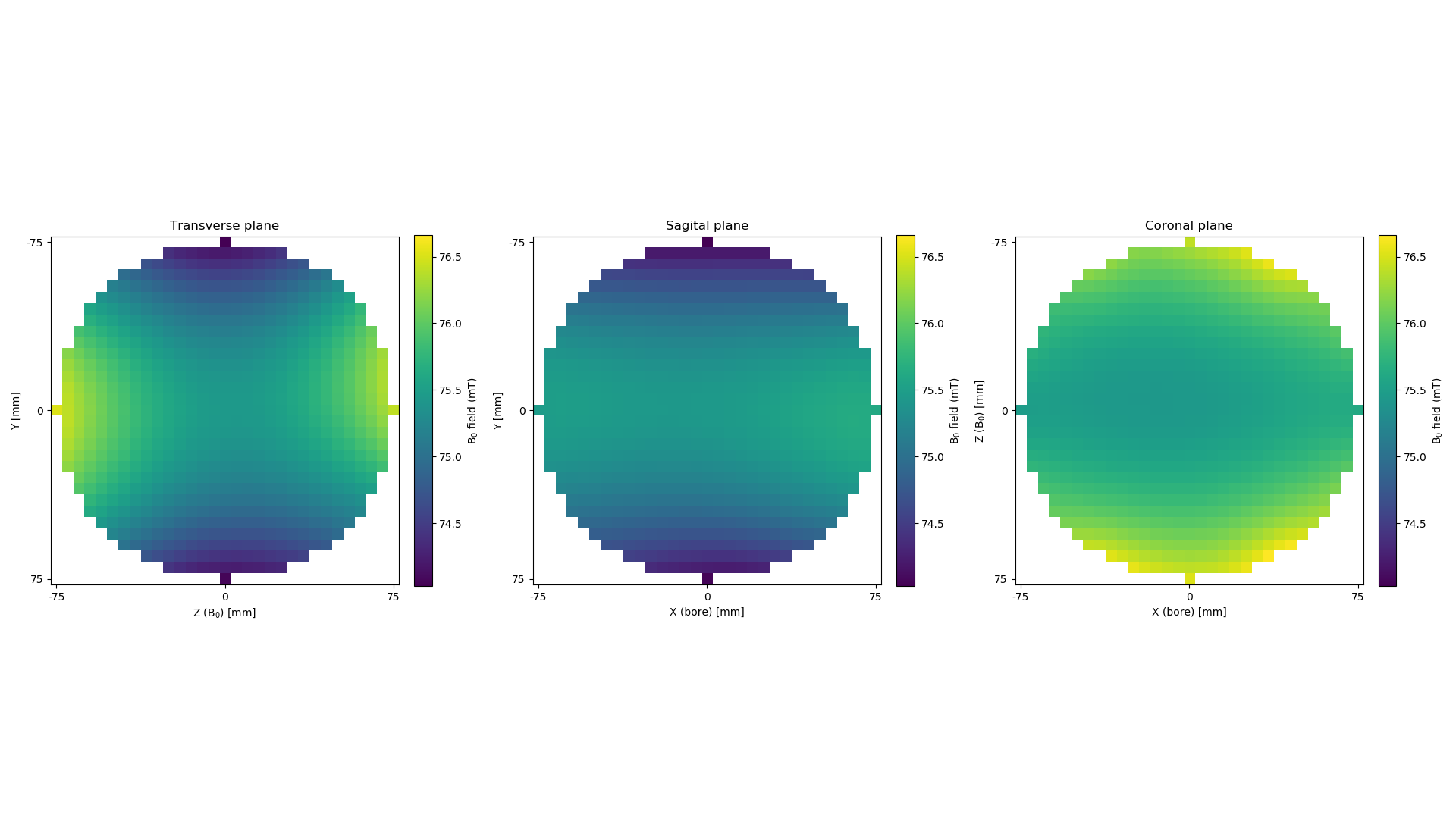
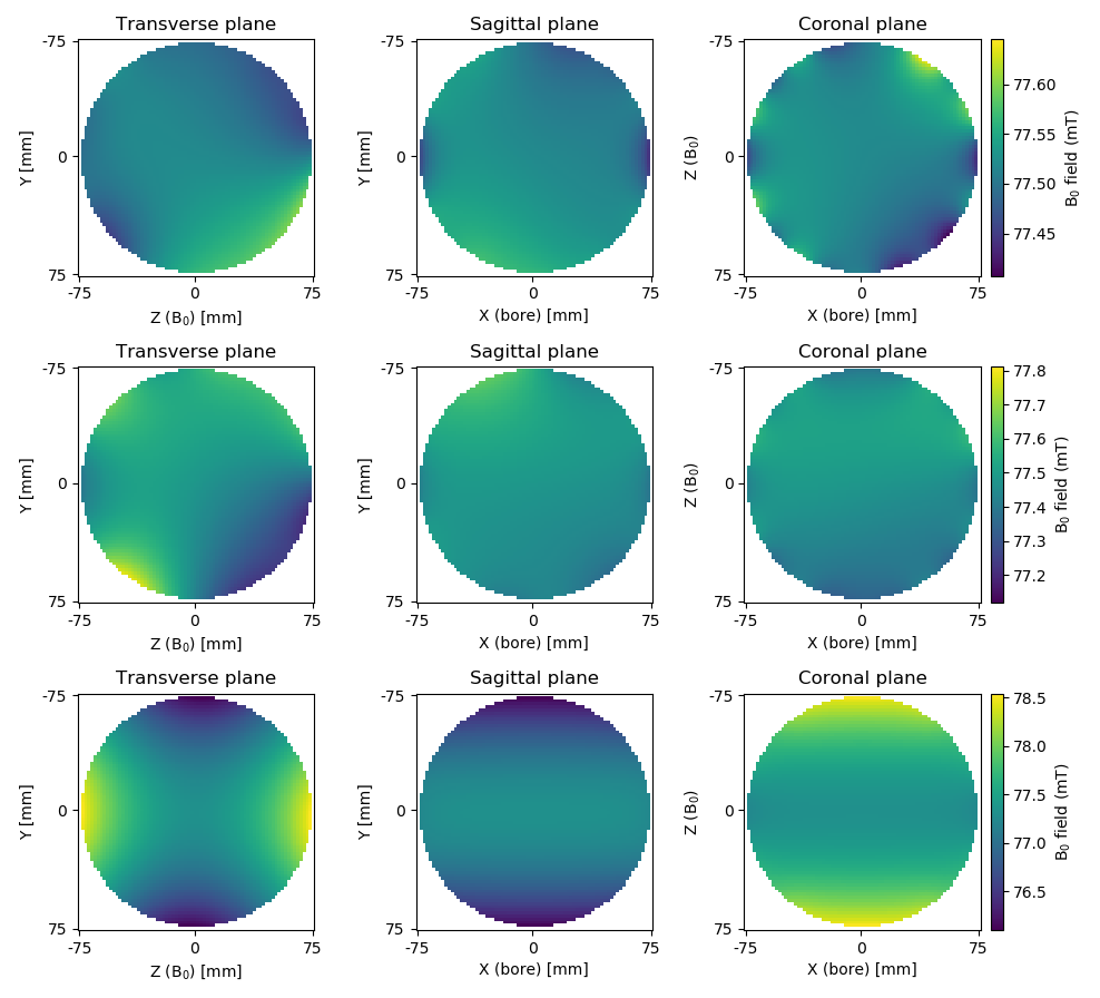
Figure 1 shows a side view of the magnet and gives an overview of the rings sizes of the constructed magnet and simulated magnetic field plots. Figure 2 shows simulated and measured field plots of the magnet: note the difference in scales in the colorbar. The constructed magnet has a mean field strength of 75.5 mT and a homogeneity of 33860 ppm over the 15 cm DSV. Figure 3 shows that the torque acting on the magnets varies with 2θ where θ is the polar angle: the rotation error that is used as a function of position is shown in blue. Figure 4 shows the impact of the three different errors. The inhomogeneity of the magnet with random fluctuations in remanence is 3074 ppm, the inhomogeneity with random fluctuations in the magnetization direction of the magnets is 8960 ppm but the inhomogeneity with the non-random rotations due to the torque on the magnets is 31534 ppm. The field distribution seen for the non-random distribution closely resembles the measured field distribution of the mapped magnet.Discussion
In this work we show that non-random magnet rotations that result from imperfections in the manufacturing of the magnet ring holders can explain the large difference in homogeneity seen between simulated and constructed magnets. If the average angle that the magnets will be able to rotate is known before the rings are manufactured then these errors can be corrected for during manufacturing to potentially improve the agreement between simulated and constructed magnets.Acknowledgements
The authors would like to thank Wouter Teeuwisse, Bart de Vos and Sumit Tewari for their assistance in construction of the magnet. This work is supported by the following grants: Horizon 2020 ERC FET-OPEN 737180 Histo MRI, Horizon 2020 ERC Advanced NOMA-MRI 670629, Simon Stevin Meester Award and NWO WOTRO Joint SDG Research Programme W 07.303.101.References
[1] Halbach K. Design of permanent multipole magnets with oriented rare earth cobalt material. Nucl. Instrum. Methods Phys. Res. 1980;169:1-10
[2] Turek K et al. Magnetic field homogeneity perturbations in finite Halbach dipole magnets. J. Magn. Reson. 2014;238:52–62
[3] Raich H et al. Design and construction of a dipolar Halbach array with a homogeneous field from identical bar magnets: NMR Mandhalas. Concepts Magn Reson Part B Magn Reson Eng. 2004;23B:16-25
[4] Soltner et al. Dipolar Halbach Magnet Stacks Made from Identically Shaped Permanent Magnets for Magnetic Resonance. Concepts Magn Reson Part A. 2010;36A(4):211-222
[5] Cooley C et al. Design of sparse Halbach magnet arrays for portable MRI using a genetic algorithm. IEEE Trans Magn. 2018; 54(1)
[6] O’Reilly T et al. Three-dimensional MRI in a homogenous 27 cm diameter Bore Halbach Array Magnet. J. Magn. Reson. 2019;307
[7] Hugon C et al. Design of arbitrarily homogeneous permanent magnet systems for NMR and MRI: Theory and experimental developments of a simple portable magnet. J. Magn Reson. 2010;205:75-85
[8] Han H et al. Open Source 3D Multipurpose Measurement System with Submillimetre Fidelity and First Application in Magnetic Resonance. Sci. Rep. 2017.;7:13452
Figures