4038
Dipole position sensors integrated in receiver array for motion detection and correction
Ed Boskamp1, Mike Twieg1, and Rafael O'Halloran1
1Hyperfine, Guilford, CT, United States
1Hyperfine, Guilford, CT, United States
Synopsis
MRI is sensitive to patient motion. There are a number of pulse sequence techniques like navigators and propeller to prevent motion artifacts. We are introducing a sensitive sensor based technique to detect motion and pose without touching the patient. The sensors are a number of miniaturized dipole resonators integrated into the receiver array. Motion corrupted lines in k space are flagged and rescanned, or when motion is between a limited number of poses, the data can be binned and combined before the recon process.
Introduction
MR imaging sequences are sensitive to patient motion. The resulting artifacts in the image can render images undiagnostic. Techniques like Propeller, spiral and navigators help to reduce motion artifacts(1). We are introducing a sensor based technique that detects the position of the patient. The coil integrated sensors do not touch the patient. When patient motion is detected, the corresponding line in k space is rescanned, or when motion is between a limited number of poses, data can be binned and corrected later.Methods
Varactor tunable 175 MHz dipole antennas were designed having an electrical length of half a wavelength and a physical size of 3 by 3 cm (fig 1). The dipoles were placed inside the housing of a 2.73 MHz Brain Transceiver array on a 64 mT MRI scanner (Hyperfine Inc.). The Brain transceiver has a solenoidal transmit coil, an 8 channel receiver array, 8 preamplifiers, and the dipole signal processing board all integrated (Fig 2). In total 4 dipoles were placed in areas of the coil where patient motion was measured to be most significant: above the nose, left and right of the forehead, and at the apex. Dipoles are connected to a signal processing board in the coil (fig 3) containing programmable oscillators, bi-directional couplers, Vrms detectors, ADCs and a micro controller. The processed data is sent to the host computer when triggered by the sequence. Using the couplers the detectors sense the reflected power from the dipoles at a fixed observation frequency. As the patient gets closer to a dipole, the frequency of the dipole drops and the reflected power increases, providing a position-dependent signal that can be used to detect motion. Bench measurements were performed using a phantom to measure the sensitivity of the dipoles versus patient distance, dipole frequency and dipole size. MRI: a proof-of-concept scan was performed on a 64 mT portable MRI scanner (Hyperfine Research, Inc, Guilford USA) with an 8-channel receive, 1-channel transmit head coil using a T2-weighted FSE scan (resolution 17. x 1.7 x 5 mm, FOV 22 x 18 x 18 cm, scan time 450 s, TR=1.5s, TE=38ms, ETL=80). A volunteer was instructed to remain still and change positions half-way through the scan. The 4 channels are dipole data were grouped into poses using unsupervised learning (dbscan). A pseudo velocity was calculated the gradient of the dipole data and summing over the square of the channels. A threshold was set empirically to identify data with high motion. These data were eliminated from the reconstruction. low resolution images of each pose group were performed. These groups were registered to obtain the rigid-body transform that best aligned the groups. The rigid-body corrections were then applied in k-space to allow all data to be reconstructed together. Reconstruction was performed with and without motion correction on the same acquired data.Results
There were minor differences in sensitivity between dipoles tuned for 175 MHz and 340 MHz (fig 4). The 340 MHz dipole had slightly better performance. Both had a range of about 6 cm. The only way to increase that range was to increase the size of the dipole but size is limited due to the size of the coil, interference with the RF coil hardware and dipole-dipole interaction. The 3 by 3 cm dipoles placed in the 4 locations, as described, have a dipole dipole isolation of <-35 dB. To further avoid interaction, the dipoles have slightly different resonant and observation frequencies (+/- 300 KHz) as set up by the varactor diodes. The Q of the dipoles is 20-30. Even though the 175 MHz dipoles had slightly less sensitivity it was chosen because the cable management is less critical. Even though the micro coax connecting the dipoles to the processor are on the order of 15 cm in length and the connection to the dipoles is via a lattice balun, the higher frequencies still experience some cable routing sensitivity due to residual E field coupling to the cable shields. Filtering and shielding of the processor board prevented EMI noise in the images. MRI: Two groups of dipole data were identified by the unsupervised classification. Approximately 2% of the data were rejected due to high motion. Figure 5 compares 4 example slices from the motion-corrupted image on the left to the same slices of the motion-corrected image on the right. This clearly shows improved depiction of detail with the motion-correction.Conclusions
Integrating dipole position sensors in a MR receiver array can be a powerful tool for correcting motion corrupted images. Physical size of the dipoles is related to their range of sensitivity. The number of dipoles, their location and orientation can be adjusted to sense targeted motion. Proper shielding and filtering of the processor board eliminates interference . A proof-of-concept imaging study showed the potential of this system - pose classification and data rejection. Future study will focus on refining the technique and investigating true pose estimation from higher channel-number arrays of dipole detectors, as well as combining with image based motion correction techniques such as navigators.Acknowledgements
No acknowledgement found.References
(1) Godenschweger, F., et al. "Motion correction in MRI of the brain." Physics in Medicine & Biology 61.5 (2016): R32.Figures
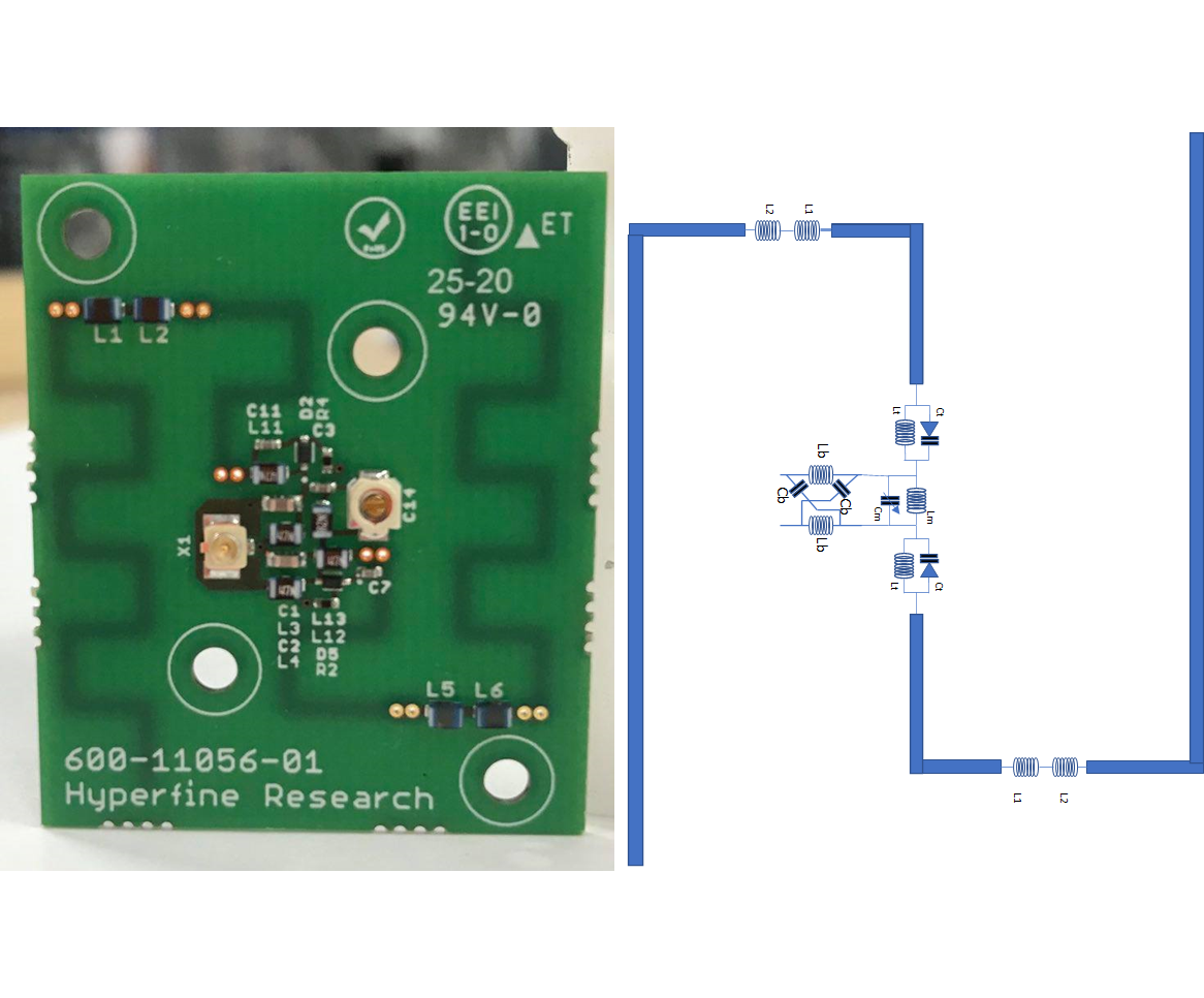
Fig 1: Dipole sensor, 3 by 3
cm, 175 MHz, with varactor tuning
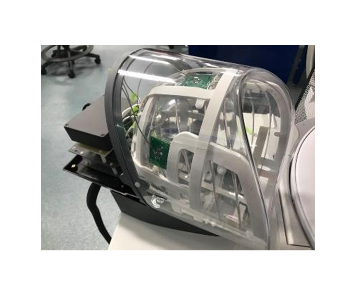
Fig 2: 8 channel transceiver array for 64 mT, 4
integrated dipole position sensors, 8 preamps for the MR signal, and dipole
signal processor in shielded black box
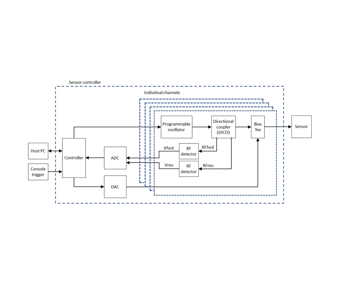
Fig 3: Dipole controller,
measuring reflected power at a fixed observation frequency for each dipole. A
DAC and integrated varactor diodes tune the dipoles to the desired frequencies
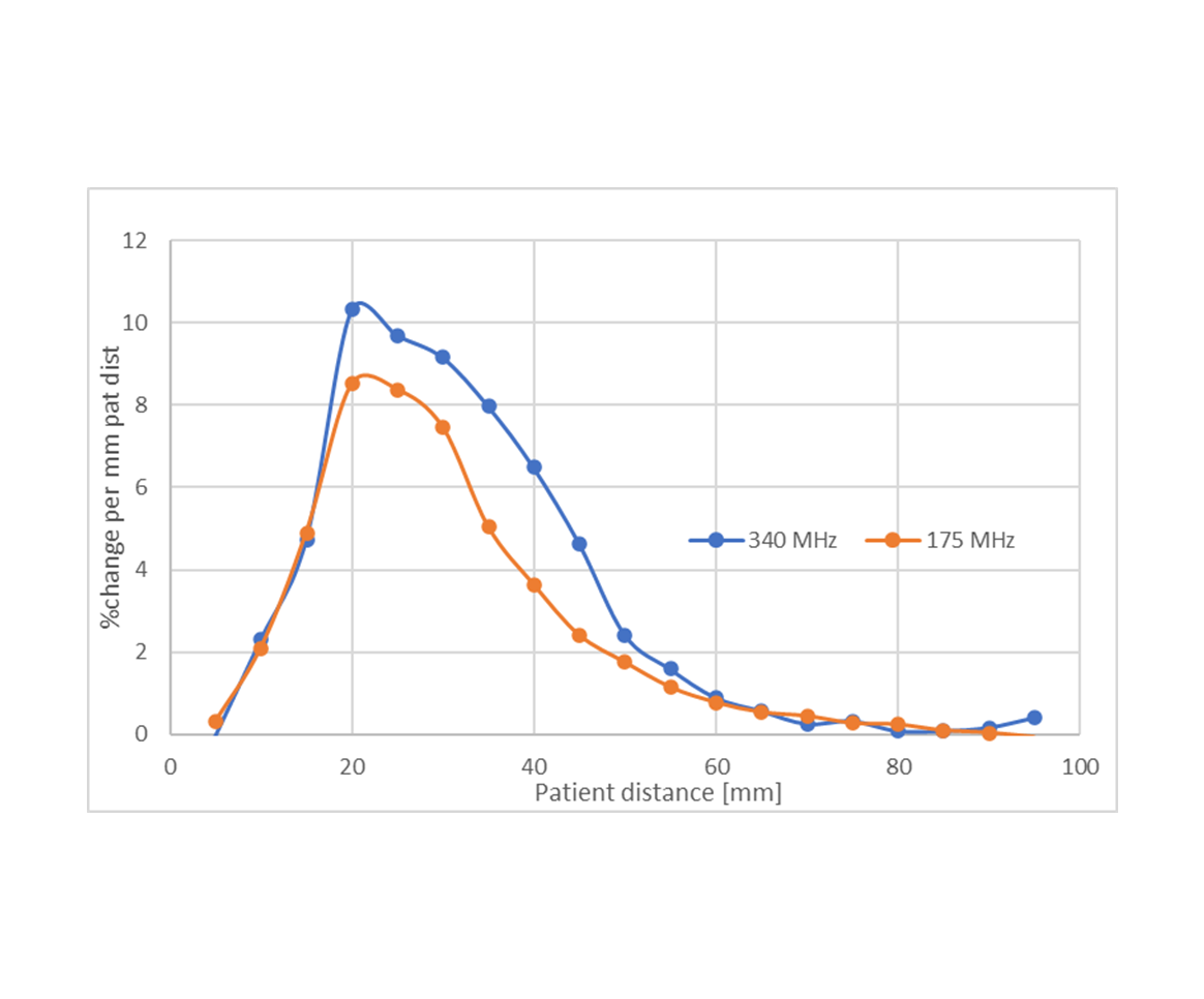
Fig 4: The percentage change in S11
magnitude as a function of distance between water phantom and dipole for the
same dipole tuned to 2 different frequencies. At large distance the capacitance
to the patient is small, so the sensitivity is small. At very close distance
the resonance frequency of the dipole has dropped a lot and our fixed
observation frequency is in the flat portion of the S11 curve.
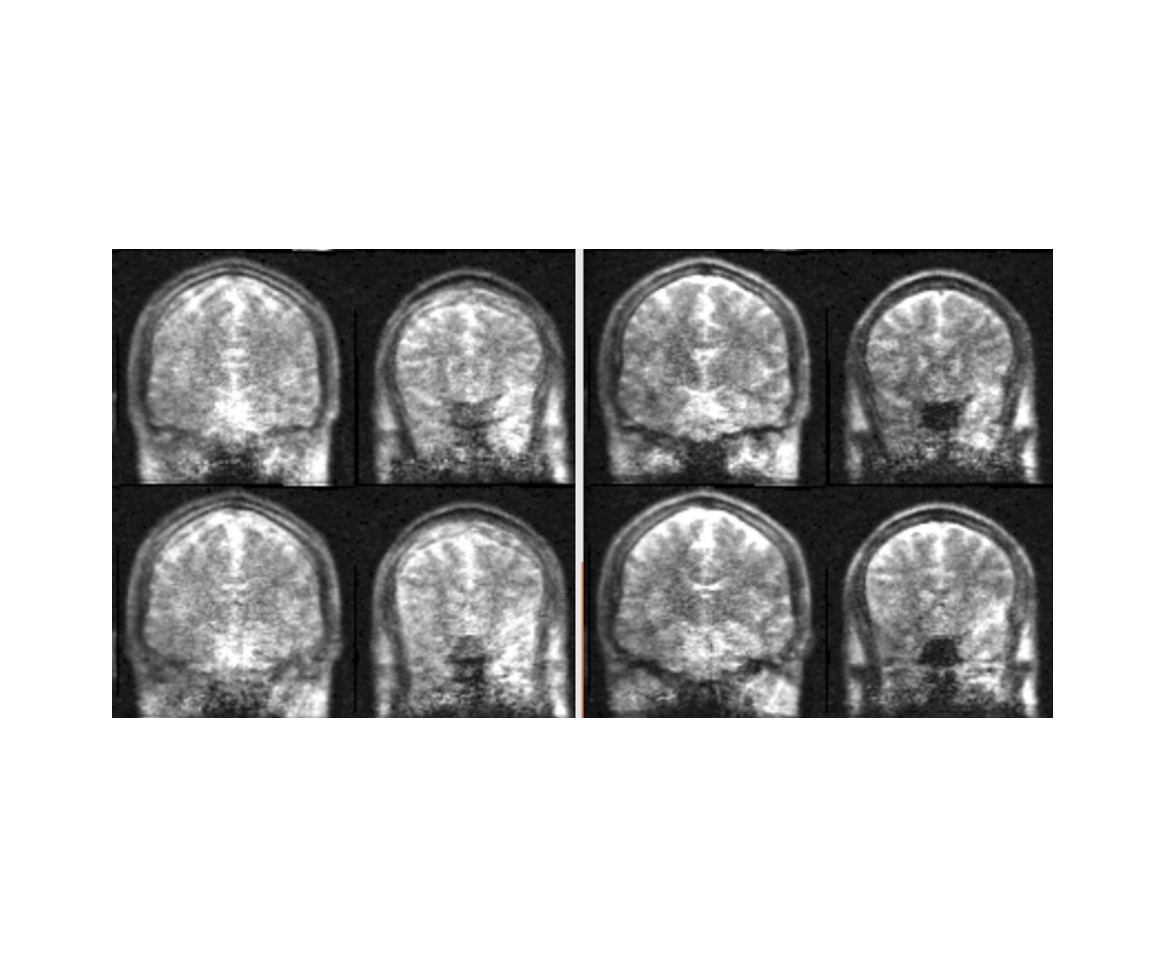
Fig 5: A panel of four
coronal slices of the T2-weighted scan without motion correction (left). The
same panel of four coronal slices with the dipole-based motion correction
(right).