4037
Design and testing of a four-channel receive array coil on a 50 mT permanent magnet system.
Javad Parsa1, Thomas O'Reilly1, Bart de Vos1, and Andrew Webb1
1Leiden University Medical Center, Leiden, Netherlands
1Leiden University Medical Center, Leiden, Netherlands
Synopsis
An integrated transmit coil and four-element receive array has been simulated, constructed, characterized and tested on a low field MRI system operating at 2.15 MHz. Using a combination of loops and butterfly coils neighbouring inter-element coupling is below -18 dB, with directly opposite coils ~-9 dB, and <-17 dB coupling for all receive coils to the transmit coil. Images of a phantom have been acquired with a simple sum-of-squares reconstruction.
Introduction
Phased array receive coils1 are ubiquitous on clinical MRI systems, providing improved signal-to-noise (SNR) over larger volume coils and the capability of undersampling k-space for more rapid image acquisition2. Phased array coils would also be very useful for very low field systems for reducing imaging time and enabling lossless receive bandwidth amplification via preamplifier impedance mismatch1, even though coil-dominated noise means that SNR is not increased as it is at higher fields. However, implementation of phased arrays receivers on very low field systems is more challenging since coil/sample coupling is much lower, loaded Q-values are higher, and so inter-coil coupling is higher. In addition, different geometries are required due to the transverse nature of the B0 field in Halbach arrays, the most common geometry for low field MRI. One example has been presented previously3, but this used only surface loops, many of which have very low sensitivity since B0 and B1 directions are coincident. In this work, we design a four coil receive array constructed by a combination of loop and butterfly coils and demonstrate performance on a 50 mT (2.15 MHz) Halbach-based MRI system.Methods
Two loop coils and two butterfly coils were constructed from flexible PCB with 0.3 mm thickness and 3 mm trace widths, and were fixed on a plexiglass cylinder with 15 cm diameter and 25 cm length (Figure1): loop and butterfly coils have 4 and 2 turns, respectively, with a total conductor length << λ/20. The spacing between the coils was optimized to minimize coupling between the adjacent butterfly and loop coils (Figure 1). A solenoid transmit coil was designed with MATLAB and CST (CST Microwave Studio, Darmstadt, Germany) to create a 20 cm axially-uniform B1+ field (Figure 2). The Tx coil was constructed with 48 turns of 1 mm copper wire on a plexiglass former with 22 cm diameter and 30 cm length. Impedance matching to 50 W was performed for each coil loaded with a saline phantom. Images were obtained using a 50 mT Halbach-magnet based MRI system4 using a Magritek Kea2 spectrometer (Aachen, Germany). A turbo spin-echo sequence was used with TR/TE: 3000 ms/ 15 ms, Echo train length: 40, FOV: 180x180x201 mm, 3x3x3 mm resolution, and acquisition bandwidth: 20 kHz.Results
The simulated B1+ field of the solenoid coil is shown in figure 2: the field is homogeneous to within 4% over an axial region of 20 cm. Reflection coefficients (S11) for each of the four individual Rx coils and the transmit coil under loaded conditions were lower than -22 dB at 2.15 MHz. Figure 3 shows the inter-element coupling, as well as the coupling of each element with the transmit coil. Turbo spin-echo (TSE) images were obtained from a melon using the array and compared to the image from the solenoid coil in transmit and receive mode (Figure 4 and Figure 5). Individual images are shown, as well as a simple sum-of-squares reconstruction (Figure 4). There is almost no coupling between adjacent elements because of the low mutual inductance, but signal coupling between opposite elements is apparent due to the very low loading of the sample.Conclusion
A prototype construction four-element array has been constructed and tested on a low field Halbach-based MRI system. The relatively large coils used in the array mean that opposite elements have significant coupling, although this can potentially be reduced to ~-20 dB by additional preamplifier decoupling, as well as by using a larger number of smaller RF coils. Images have been acquired and show slightly higher SNR than from a transmit/receive solenoidal coil, primarily due to the slightly smaller diameter.Acknowledgements
This work was funded by H2020-MSCA-ITN-ETN-2019 and Horizon 2020 ERC Advanced NOMA-MRI 670629.References
- Roemer PB, Edelstein WA, Hayes CE, Souza SP, Mueller OM. The NMR phased array, Magn Reson Med. 1990; 2:192-225.
- Hamilton J, Franson D, Seiberlich N. Recent advances in parallel imaging for MRI. Progress NMR Spectroscopy. 2017; 101:71-95.
- Cooley C Z, Stockmann J, Armstrong B D, et al. Two-Dimensional Imaging in a Lightweight Portable MRI Scanner without Gradient Coils. Magn Reson Med. 2015; 73:872–883.
- O’Reilly T, Teeuwisse W M, and Webb A G, In vivo 3D brain and extremity MRI at 50 mT using a permanent magnet Halbach array. Magn Reson Med. 2020;00:1-11.
Figures
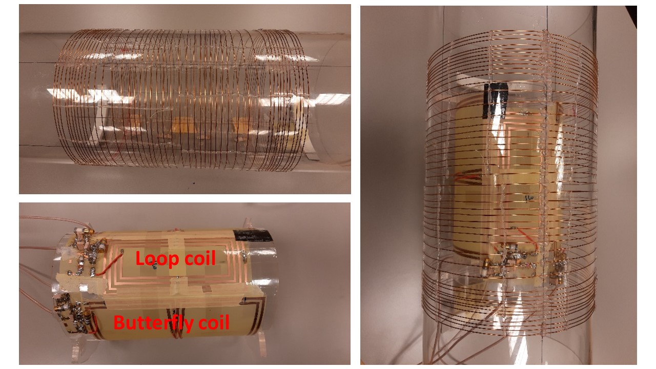
Figure 1. Left top) Optimized solenoid coil. Left bottom) 4-channel array
coils. Right) Integrated assembly.
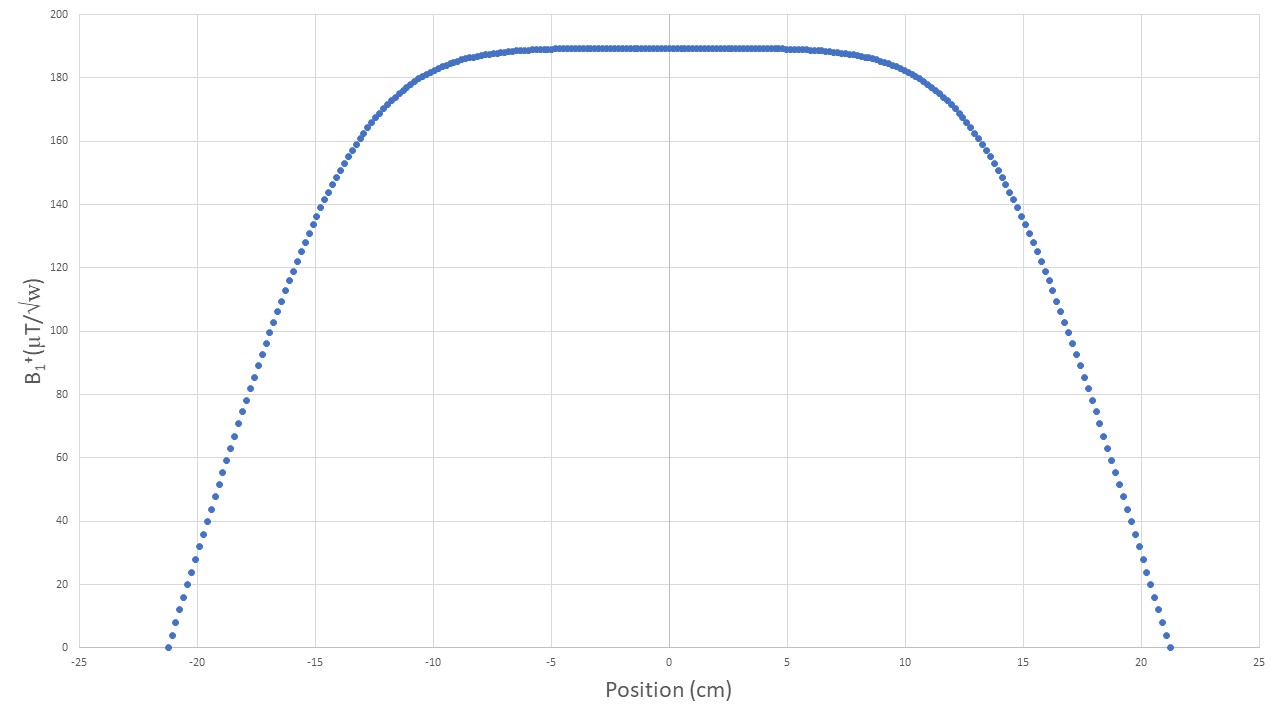
Figure 2. 1D-plot of the magnetic field (B1+) at the center
of the transmit coil.
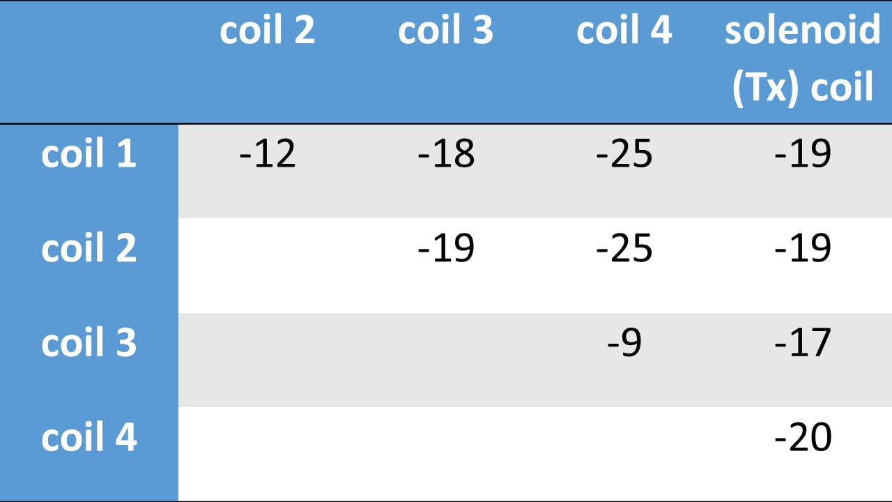
Figure 3. Measured S-parameter matrices under loaded conditions
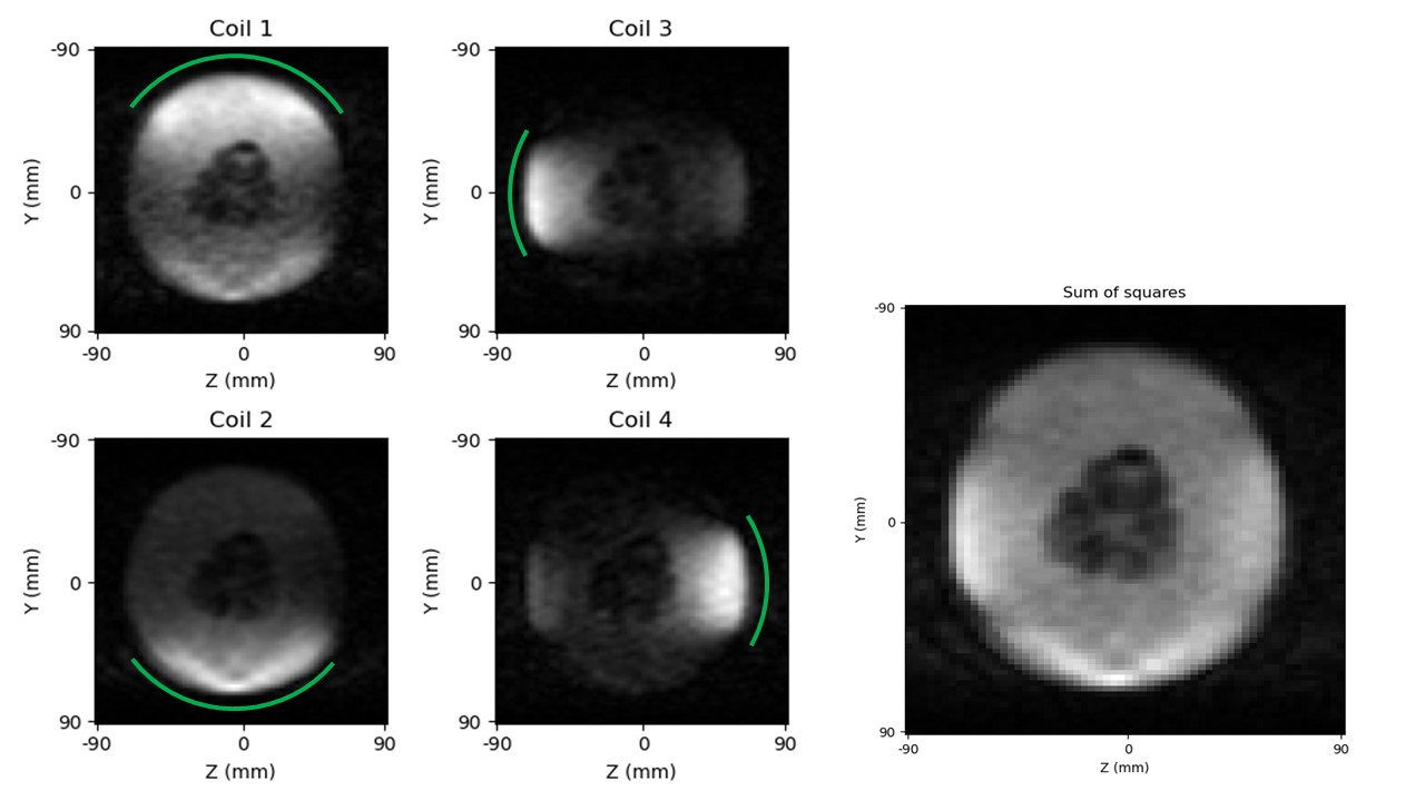
Figure 3. TSE image of the melon.
Left) individual elements. Right) sum of squares reconstruction
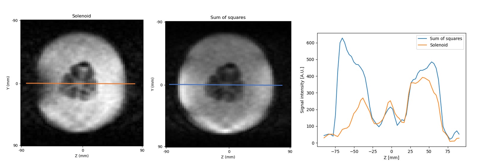
Figure 4. 1D signal intensity profile of the image of the solenoid
coil (left) and the array sum of squares image (middle). (Right) 1D signal
intensity profiles.