4036
Target-field optimized quadrature RF coils for wrist imaging on a 76 mT Halbach-based MR system1C.J. Gorter Center for High Field MRI, Leiden University Medical Center, Leiden, Netherlands, 2Circuits and Systems, Delft University of Technology, Delft, Netherlands
Synopsis
We describe a design method for quadrature RF coils for Halbach based magnets using a target field approach. The resulting current densities corresponding to these coils make them inherently decoupled. We constructed a coil pair for a newly built 76 mT system and imaged the wrist of a volunteer. The images showed a 33% SNR improvement over a linear coil, in close agreement with simulations.
Introduction
Circular polarized radio frequency (RF) fields double the transmit efficiency and give a √2 increase in signal-to-noise ratio (SNR) compared to linear fields. Nevertheless, most coils used for Halbach-based, low field MRI are linear1,2, although the principle of a quadrature hemispherical head coil has been shown previously3. The transverse B0-direction intrinsic to the Halbach array means that single structure configurations, such as the birdcage, which can produce circular polarization due to their symmetric construction, cannot be used. Instead a two-coil approach must be used. Such a two-coil design is prone to strong inter-coil coupling, particularly at low field where sample loading is very small and loaded quality (Q)-factors are high. In addition, the use of two different geometries can lead to a sensitivity mismatch which can produce suboptimal elliptical polarization. In this work we describe a quasi-static target field approach (which is appropriate for our newly designed 76 mT - 3.25 MHz multi-element Halbach magnet) to design two cylindrical intrinsically decoupled coils which produce quadrature fields of equal transmit/receive sensitivity (mT/√W input power).Methods
A sum of sinusoidal basis functions, as described in the work of Forbes4, is used to represent the current densities on the surfaces of two concentric cylinders. We prescribe two orthogonal target fields in the same cylindrical sub volume. Substituting the current density equations into the Biot-Savart law results in a system of linear equations for the weights of the modes. Subsequently, using stream functions, we obtain the wire patterns for both surfaces. For the axial target field, we consider only modes that create zonal current densities, resulting in solenoidal wire paths. This is done for stability reasons and to achieve decoupling between the coils. One can show analytically that the mutual inductance between a zonal current density on one cylinder and a current density that is an odd function of the angular direction on the second cylinder, is zero. This indicates inherent decoupling between the coils. To achieve this in practice we need to make sure that any wire paths connecting the consecutive contours produce fields which cancel each other as much as possible. Furthermore, the concentric centering of the two coils needs to be very accurate. The latter is done by 3D printing a holder which centers the inner coil inside the outer coil.To create the required 90o phase difference between the two coils for excitation and reception, we designed a lumped-element quadrature hybrid coupler, with less than 0.5 dB insertion loss, 1o phase error and 25 dB inter-channel isolation.
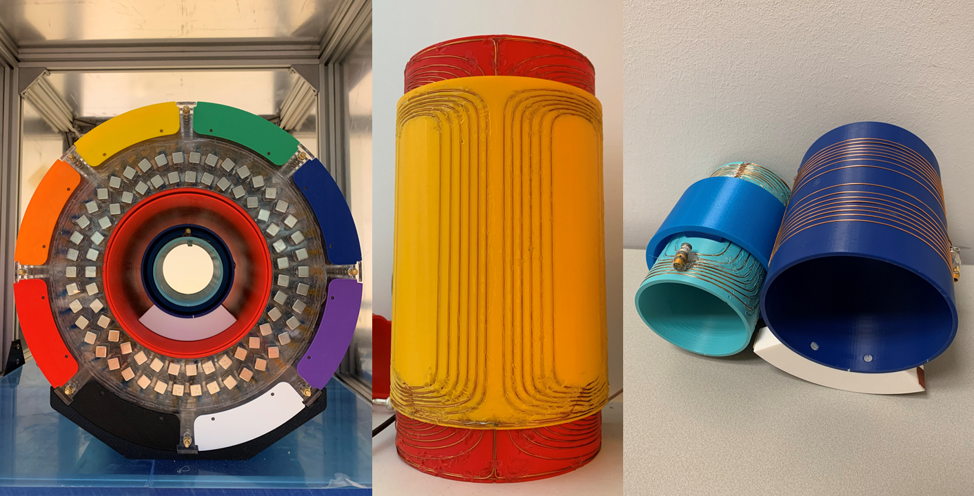
The quadrature coils and magnet configuration are shown in Figure 1. The solenoid is the outer coil as it is inherently more efficient. The magnet and gradient coil designs are based on our previous work at 50 mT5,6, but with a magnet bore diameter decreased by 33% resulting in the increased field strength of 76 mT. After the first shim iteration, with the shim magnets placed outside of the magnet unlike in the previous work, the magnet has a simulated homogeneity of 2607 ppm over a 15 cm DSV. The gradient coils have an efficiency ~0.6 mT/m/A and an inductance of ~50 mH. They are designed to have a linear DSV of 15 cm with a maximum error of 10%. The compact magnet including gradients and shims weighs only 35 kg.
Results
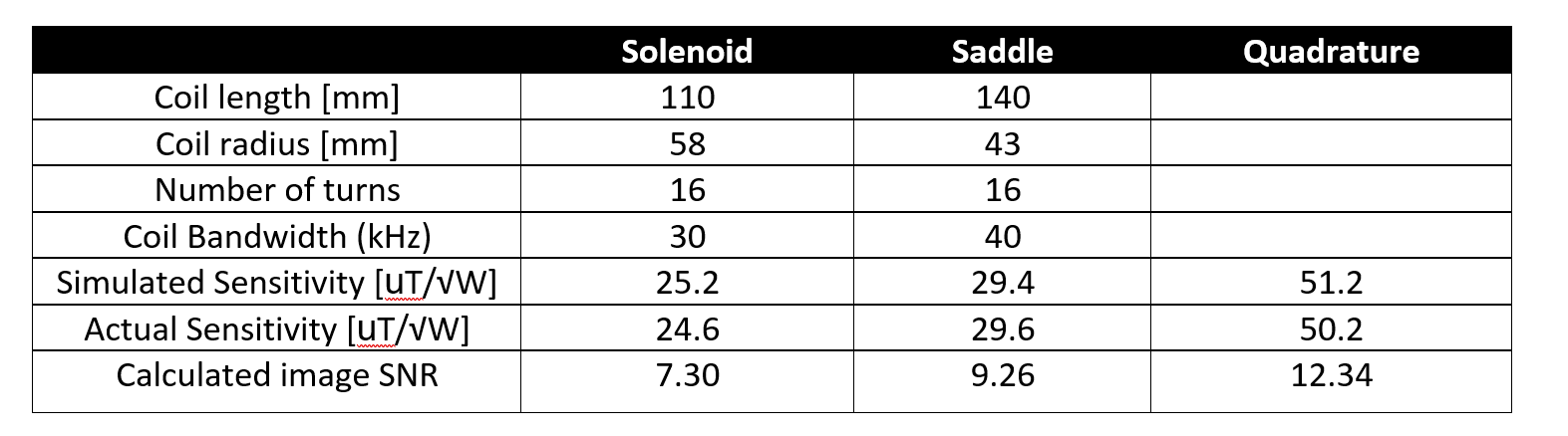
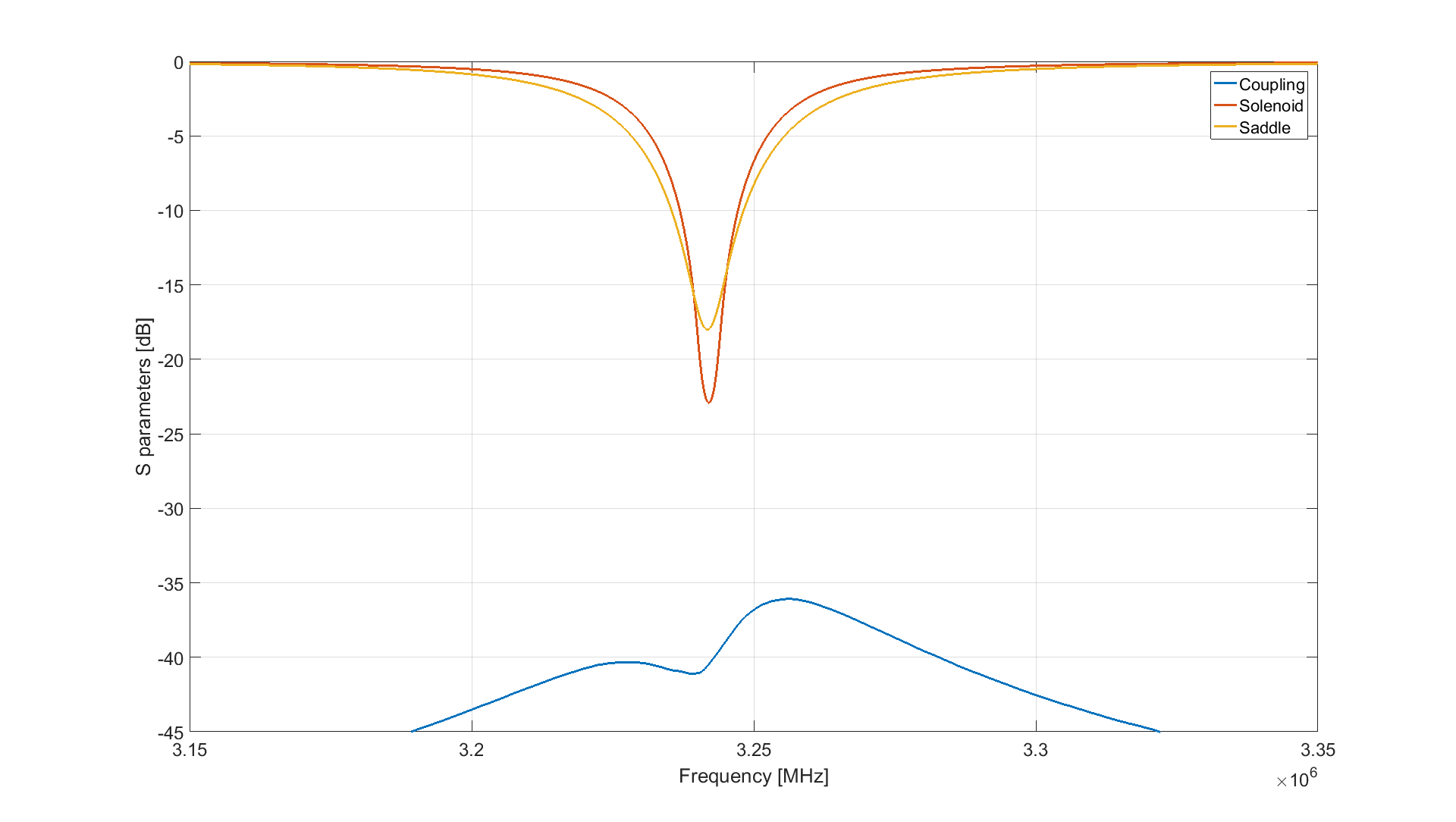
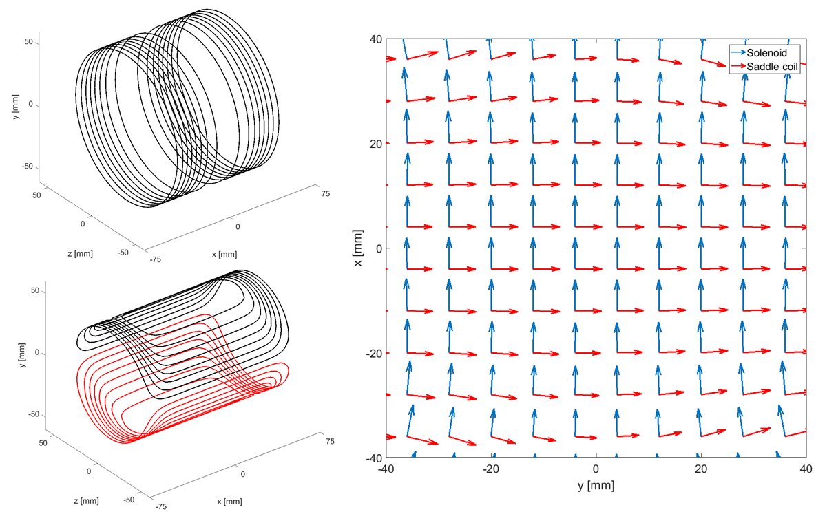
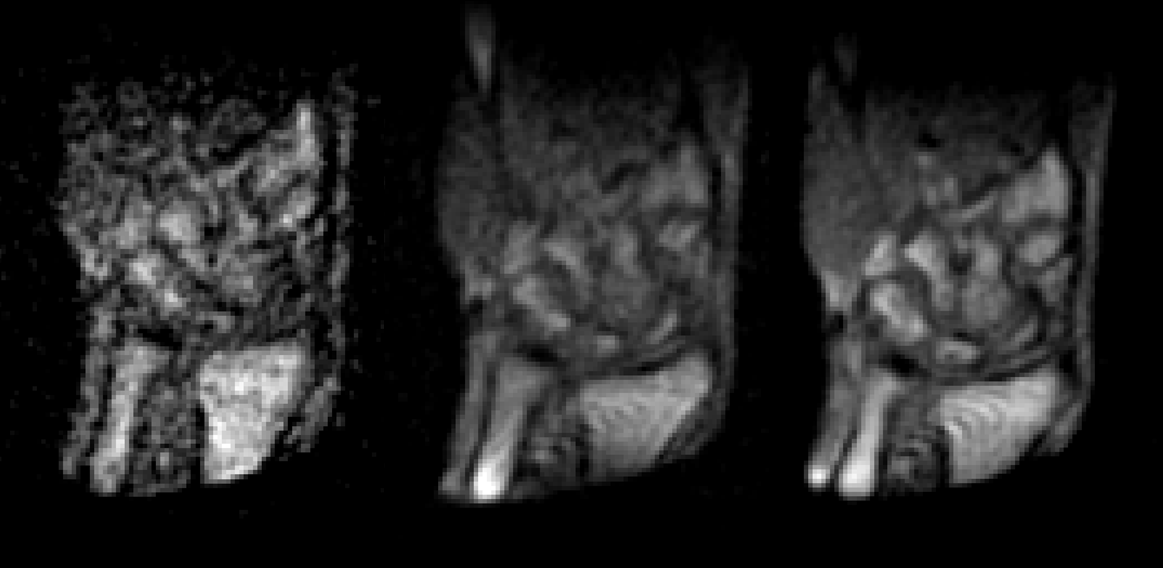
Figure 2 shows a table with the characteristics of the RF coils, singly and in quadrature combination. The simulated sensitivity is in good agreement with the measurements. We observe a 71% increase in quadrature transmit efficiency with respect to the saddle coil, which corresponds to an SNR increase of 33%. Figure 3 shows the coils tuned and matched, with no peak splitting and a coupling of less than -35 dB. Figure 4 shows the wire patterns and simulated RF fields to demonstrate that full quadrature operation can be achieved over the prescribed 80 mm DSV. Figure 5 shows images of a volunteer’s wrist with the separate coils and the coils combined in quadrature. We calculated an SNR increase of 33% with respect to the saddle coil image. The solenoid has a slightly lower sensitivity due to the larger radius. This in combination with the insertion loss of the quad hybrid coupler (~0.5 dB) explains why the gain is slightly below the theoretical √2 increase.Discussion
This work shows that quadrature coils can be designed to increase the SNR for low field imaging in the low MHz range. Accurate design is critical to achieve a high degree of decoupling between coils, since even relatively minor rotations can significantly increase the coupling. Using the 3D printed molds and separator we can achieve -35 dB decoupling between the two coils. Decreasing the radius of the solenoid would slightly increase our sensitivity, however this would make the decoupling even more sensitive to small construction inaccuracies.Conclusion
We have shown that using our target field method we are able to design quadrature RF coils for Halbach-based MRI systems. Using our 76 mT system in combination with our quadrature coils we can obtain in-vivo wrist images with a 33% increase in SNR over a single coil.Acknowledgements
This work is supported by the following grants:Horizon 2020 ERC FET-OPEN 737180 Histo MRI,Horizon 2020 ERC Advanced NOMA-MRI 670629,Simon Stevin Meester Award and NWO WOTRO JointSDG Research Programme W07.303.101.References
1. T. O'Reilly, et al. (2020). In vivo three-dimensional brain and extremity MRI at 50 mT using a permanent magnet Halbach array. Magnetic Resonance in Medicine. 10.1002/mrm.28396.
2. C. Cooley, et al. (2020) A portable scanner for magnetic resonance imaging of the brain. Nat Biomed Eng (2020). https://doi.org/10.1038/s41551-020-00641-5.
3.N. Koonjoo, et al (2017), Optimized Quadrature Head Coil Improves SNR at ultra-low field, ISMRM poster.
4. L.K. Forbes, S. Crozier (2002), A novel target-field method for finite-length magnetic resonance shim coil: II. Tesseral shims . Journal of Physics D-applied Physics - J PHYS-D-APPL PHYS. 35. 839-849. 10.1088/0022-3727/35/9/303.
5. B. de Vos, et al. (2020), Gradient Coil Design and Realization for a Halbach-Based MRI System," in IEEE Transactions on Magnetics, vol. 56, no. 3, pp. 1-8, March 2020, Art no. 5100208, doi: 10.1109/TMAG.2019.2958561
6. T. O'Reilly, et al. (2019). Three-dimensional MRI in a homogenous 27 cm diameter Bore Halbach Array Magnet. Journal of Magnetic Resonance. 307. 106578. 10.1016/j.jmr.2019.106578.
Figures