4034
An axial gradient coil with improved linearity for Halbach-based MR systems1C.J. Gorter Center for High Field MRI, Leiden University Medical Center, Leiden, Netherlands, 2Circuits and Systems, Delft University of Technology, Delft, Netherlands
Synopsis
We reduced image artifacts and increased the attainable axial field-of-view by designing a highly linear x-gradient coil for Halbach array-based MR systems. A truncated sum of sinusoidal basis function is used for the current density. Higher order modes combined with specifying the target field inside a volume lead to a stable solution of the inverse source problem. The coil was installed on our 50 mT system and resulted in a 150% increase in linear DSV with respect to our previously designed gradient coil. Whole-brain three-dimensional images have been acquired using turbo spin echo sequences in less than 10 minutes.
Introduction
Halbach array-based MR systems show promise as the basis for low cost, low-field portable imaging systems1,2. The transverse B0-direction inherent to the Halbach array requires mathematical modification of traditional gradient coil design methods. In earlier work we reformulated the target field method proposed by Turner specifically for transverse field directions3. An open-source gradient design tool was made available using this method4. The transverse y,z-gradient coils designed with this tool yield comparable linear performance with respect to conventional MRI gradients. However, the along-the-bore x-gradient has a significantly reduced region of linearity. The goal of this work is to adapt our previous approach to design an x-gradient coil with a larger linear region to increase the attainable field-of-view in this direction. A new x-gradient coil was designed and installed in our 50 mT system5.Methods
In earlier work we obtained stable wire path solutions by exploiting the cylindrical structure of the gradient coil configuration via Fourier analysis and high-frequency filtering3. This powerful solution method is essentially an adaptation of Turner’s target field method to transverse background fields. The method has its limitations, however, particularly for axial gradient coils. The Fourier transform that is used in this method requires infinitely long cylindrical structures. Furthermore, the desired target fields are prescribed on a concentric cylinder and not in the imaging volume.To circumvent these issues, we propose a different design methodology based on the work of Forbes6. Specifically, we use a weighted sum of truncated sinusoidal basis functions to describe the current density on a finite-length cylinder. Substituting the resulting expression for the current density in the Biot-Savart law and prescribing a target field then leads to a system of equations for the weights. This system is usually highly ill-conditioned6. However, if the target field is prescribed throughout the entire volume of the cylinder and prior knowledge about the desired structure is included in our formulation by carefully choosing the number of modes that are taken into account, the problem can be solved in a stable manner.
To test the performance of this coil design methodology, two x-gradient coils were simulated for the same cylindrical geometry. One uses our original method (published toolbox) and the other uses the method described above. The radii of both coils are 135 mm, and both have a length of 350 mm and 14 turns per quadrant. After verifying that the new method results in increased linearity, a new x-gradient coil was built and tested on the 50 mT system. In order to realize an even longer usable imaging FOV the length of the gradient coil was increased to 450 mm.
Results
The two simulated x-gradient coils and corresponding magnetic fields are shown in Figure 1. The yz cross sections at x=50 mm show that there is a significant increase in uniformity using the new method. These are represented in Figure 2, which shows the simulated spatial distortions in a grid phantom of 200x200 mm. In Figure 3 data summarizing the parameters for both coils is shown. As expected, there is a trade-off between increased linearity and reduced efficiency. The diameter spherical volume (DSV) in which the non-linearity is less than 10% with respect to the center line is 2.5 times larger for our newly proposed method. Given the increased linearity, we built a 450 mm long gradient coil with our improved method: the result is displayed in Figure 4. The corresponding parameters are outlined in the table of Figure 3. The results show that the linear region in the x-direction increases as also seen in the deformation grid in Figure 4. However, the DSV over which the field is linear does not increase since the radius of the coil is kept constant and therefore the linearities in the z and y dimensions are unchanged. The impact of the new method on in-vivo brain images is shown in Figure 5. The arc-shaped high intensity region caused by the non-linearity and gradient null point is pushed outside of the imaging FOV, such that the entire brain can now be imaged.Discussion
The newly implemented design method results in a linear DSV increase of 150% compared with the previous coil for an identical size, with a trade-off of an ~25% reduction in gradient efficiency. Given the 15 A maximum output current of our gradient amplifier, a typical imaging bandwidth of 20 kHz and spatial resolution of 1-2 mm in our brain images, this reduction in gradient efficiency does not have a significant effect on the turbo spin echo sequences used to acquire the images. A four-quadrant wire path solution is optimal in terms of efficiency. For stability reasons we choose the modes that yield this solution. This is done by taking more modes in the axial direction, and less for the angular direction. Using this we can weigh ~60 modes to find the least squares solution.Conclusion
Using the new design method, an increase in the linear DSV of axial gradient coils for Halbach-based systems can be increased by ~150%. Using a newly designed coil we were able to acquire high resolution in vivo images of the entire brain without significant distortions.Acknowledgements
This work is supported by the following grants:Horizon 2020 ERC FET-OPEN 737180 Histo MRI,Horizon 2020 ERC Advanced NOMA-MRI 670629,Simon Stevin Meester Award and NWO WOTRO JointSDG Research Programme W07.303.101.References
1. T. O'Reilly, et al. (2020). In vivo three-dimensional brain and extremity MRI at 50 mT using a permanent magnet Halbach array. Magnetic Resonance in Medicine. 10.1002/mrm.28396.
2. C. Cooley, et al. (2020) A portable scanner for magnetic resonance imaging of the brain. Nat Biomed Eng (2020). https://doi.org/10.1038/s41551-020-00641-5.
3. B. de Vos, et al. (2020), Gradient Coil Design and Realization for a Halbach-Based MRI System," in IEEE Transactions on Magnetics, vol. 56, no. 3, pp. 1-8, March 2020, Art no. 5100208, doi: 10.1109/TMAG.2019.2958561.
4. Gradient design Tool: https://github.com/LUMC-LowFieldMRI/GradientDesignTool
5. T. O'Reilly, et al. (2019). Three-dimensional MRI in a homogenous 27 cm diameter Bore Halbach Array Magnet. Journal of Magnetic Resonance. 307. 106578. 10.1016/j.jmr.2019.106578.
6. L.K. Forbes, S. Crozier (2002), A novel target-field method for finite-length magnetic resonance shim coil: II. Tesseral shims . Journal of Physics D-applied Physics - J PHYS-D-APPL PHYS. 35. 839-849. 10.1088/0022-3727/35/9/303.
Figures
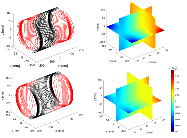
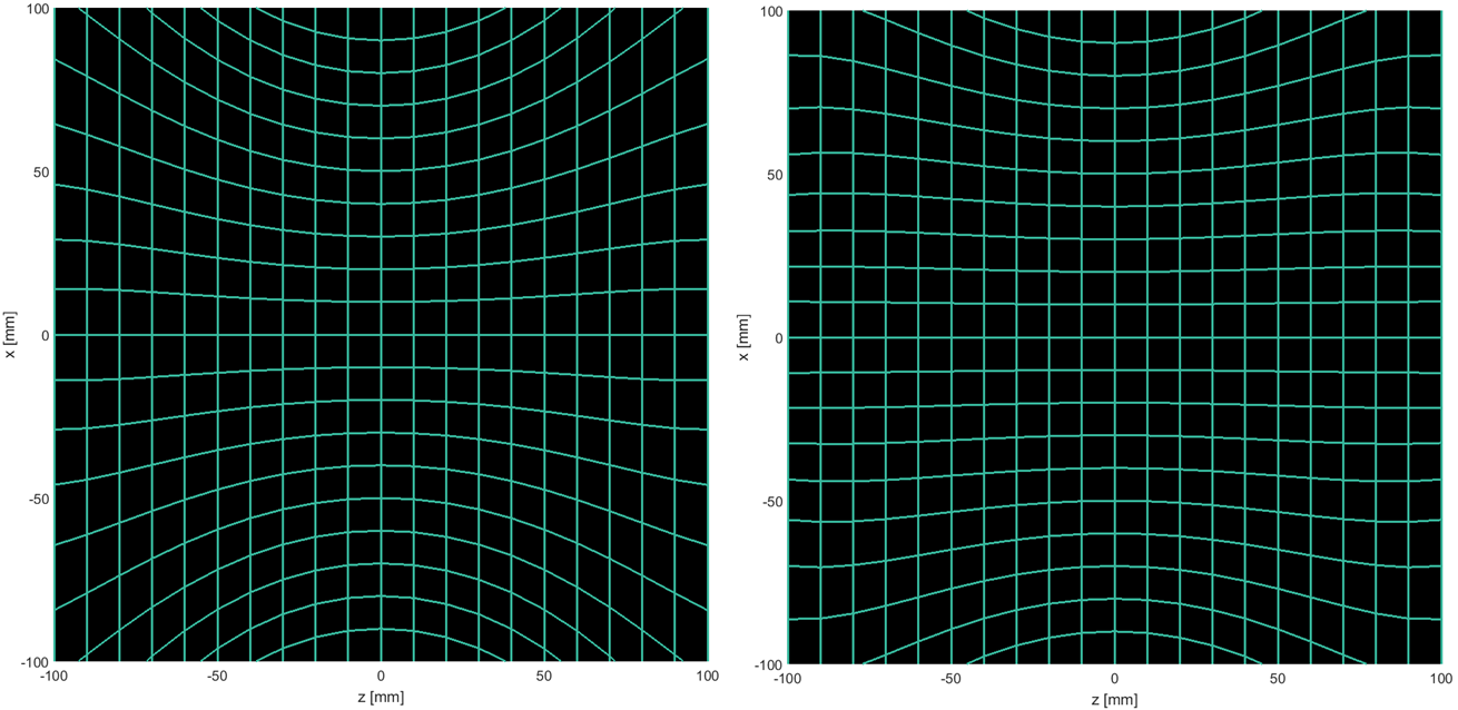
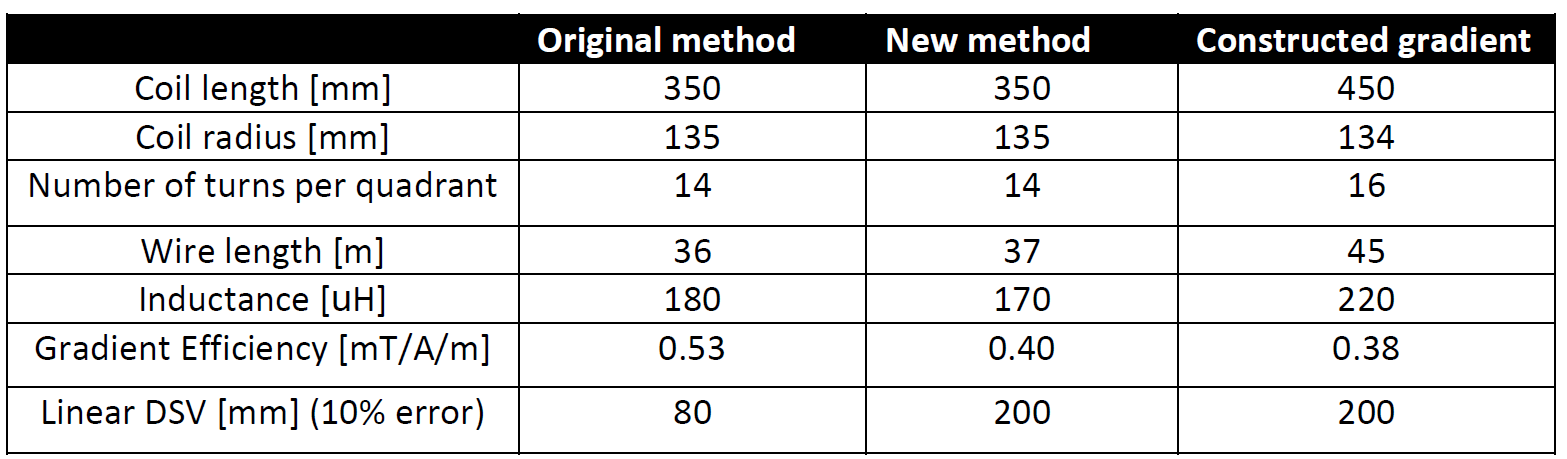
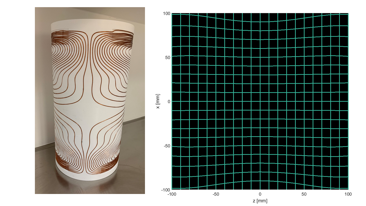
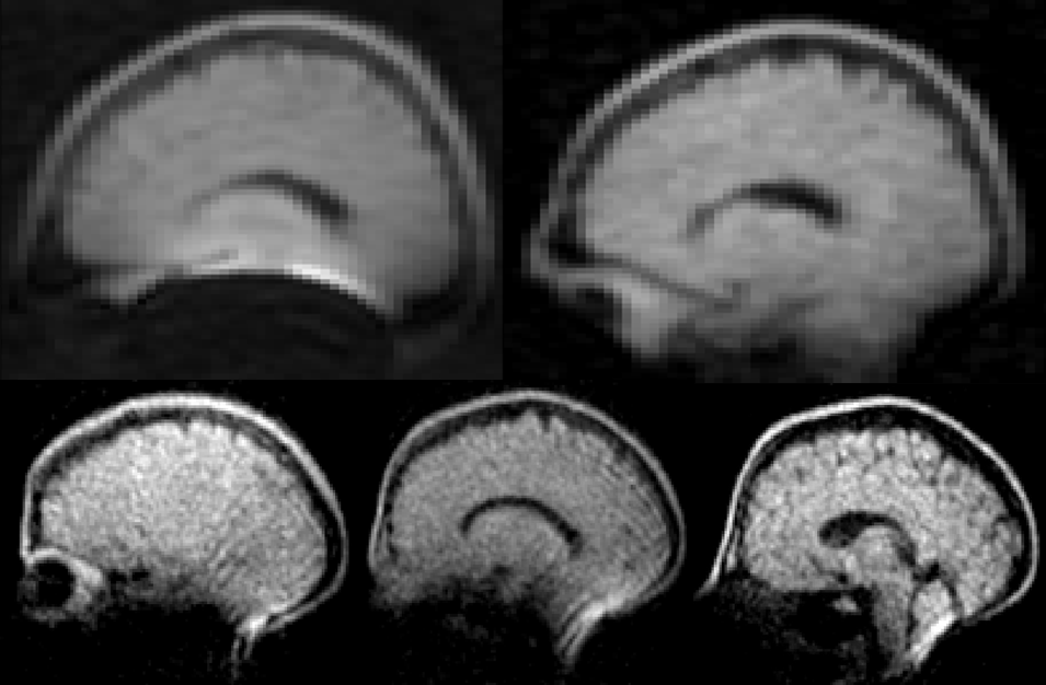
Figure 5: In-vivo brain images of two volunteers. Acquired using a TSE sequence. Top: comparing the original gradient coil (left) and the new design (right). The bottom images show three slices in higher resolution obtained with the new coil.
Acquisition parameters (top): field of view 180(z) x 240(x) x 220(y) mm, data matrix: 90x120x55, TR/TE: 400/15 ms, echo train length: 5, scan duration 8 min 48 s.
Acquisition parameters (bottom): FOV 240(y) x 180(x) x 180(z), data matrix: 160x120x60, TR/TE: 400/20 ms, echo train length: 5, scan duration: 9 min 36 s.