4033
Zero-Dead-Time Earth’s Field NMR Using Two-Photon Excitation1Electrical Engineering and Computer Sciences, University of California, Berkeley, Berkeley, CA, United States, 2Helen Wills Neuroscience Institute, University of California, Berkeley, Berkeley, CA, United States
Synopsis
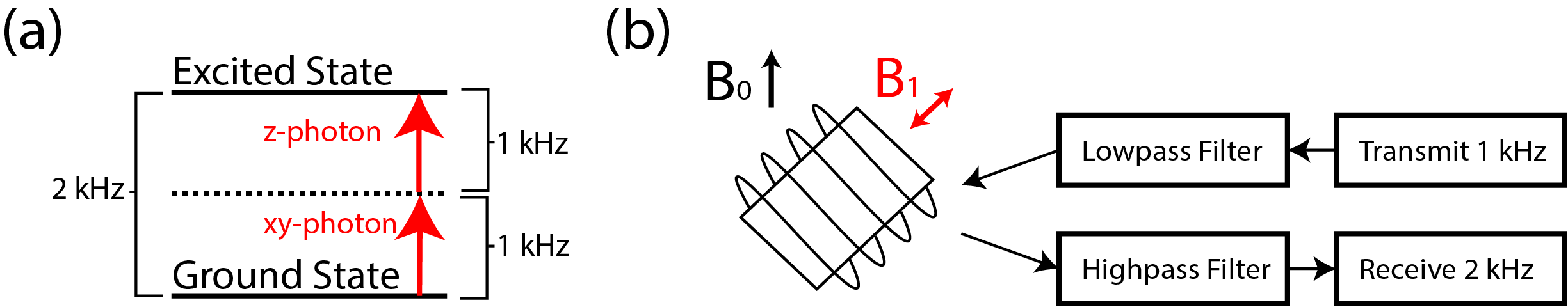
Two-photon excitation allows for excitation at half of the Larmor frequency. In Earth’s magnetic field, this corresponds to a Larmor frequency of about 2 kHz and an excitation frequency of about 1 kHz. By transmitting at 1 kHz and receiving at 2 kHz, we could transmit and receive at the same time by using filters to protect the receiver. While some harmonic distortion prevented us from fully separating the transmitted from the received signal during excitation, the always connected and unsaturated receive circuitry allowed us to eliminate receiver dead time, which can be quite long at low frequencies.
Introduction
Ultralow-field NMR/MRI presents many potential opportunities such as reduced cost, reduced chemical shifts, reduced susceptibility effects, increased portability, long liquid relaxation times, different contrasts, imaging through thin metal, and high-resolution J-coupling measurements1. It is also an interesting regime to study where applied time-varying fields such as gradients and $$$B_{1}$$$ fields can easily become comparable in magnitude to the $$$B_{0}$$$ field. For gradients, this presents challenges in that unless the gradients are very small, concomitant fields cannot be ignored2. For spatially uniform fields such as $$$B_{1}$$$ fields, we can view this ultralow-field regime not as detrimental, but rather, as advantageous. Since SAR generally scales with $$$(fB_1)^2$$$, SAR limits are nearly non-existent3, and with higher $$$B_{1}$$$ field strengths, we can take advantage of physical phenomena that may otherwise not be as practical at high $$$B_{0}$$$ fields. One example is two-photon excitation with a single frequency at half the Larmor frequency. Although half-frequency two-photon excitation has been used for simultaneous transmit and receive in NMR at 9.4 T4, it relies on intense RF fields and is difficult to extend to imaging with large sample sizes. Two-photon excitation was recently used for imaging5, but to make it more practical, multiple frequencies whose sum or difference equaled the Larmor frequency were used instead. In the present work, we developed half-frequency two-photon excitation at the Earth’s magnetic field, which is approximately 50 $$$\mu T$$$, corresponding to a Larmor frequency of about 2 kHz. By using a transmit frequency of about 1 kHz and a receive frequency of about 2 kHz, we built a directly connected signal pipeline from the transmitter to the receiver without adding any non-linear elements in between. Because of the large relative difference in the transmit and receive frequencies, we can use filters to prevent the transmitted signal from saturating the receiver, thus allowing transmit and receive at the same time. Figure 1 shows a diagram of this approach. While some harmonic distortion in the circuit prevented us from fully separating the transmit from the received signal during excitation, the always connected and unsaturated receive circuitry allowed us to completely eliminate receiver dead time, which can be quite long for low frequencies. For example, the dead time is about 20 ms for a commercial Earth field system6.Methods
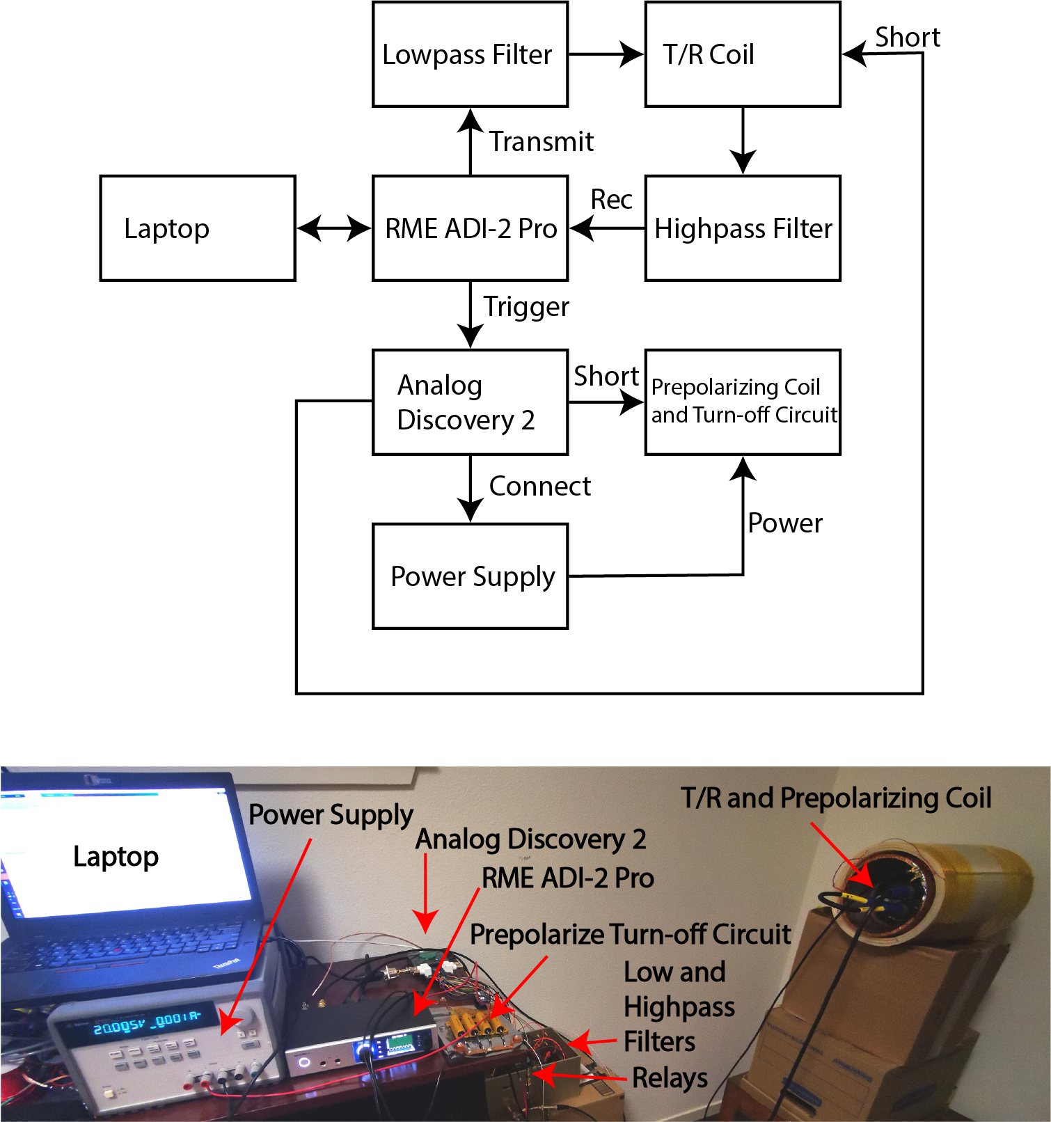
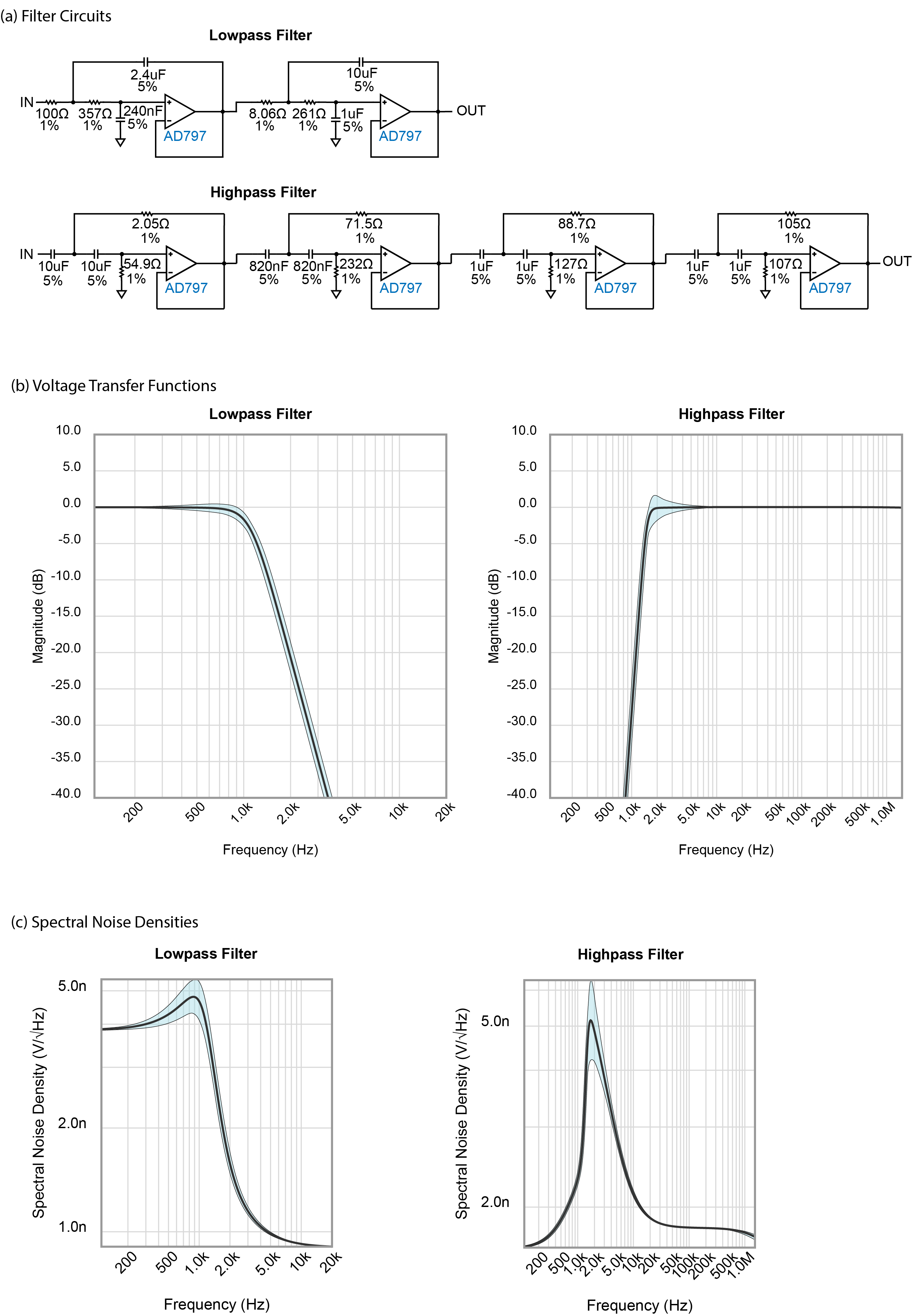
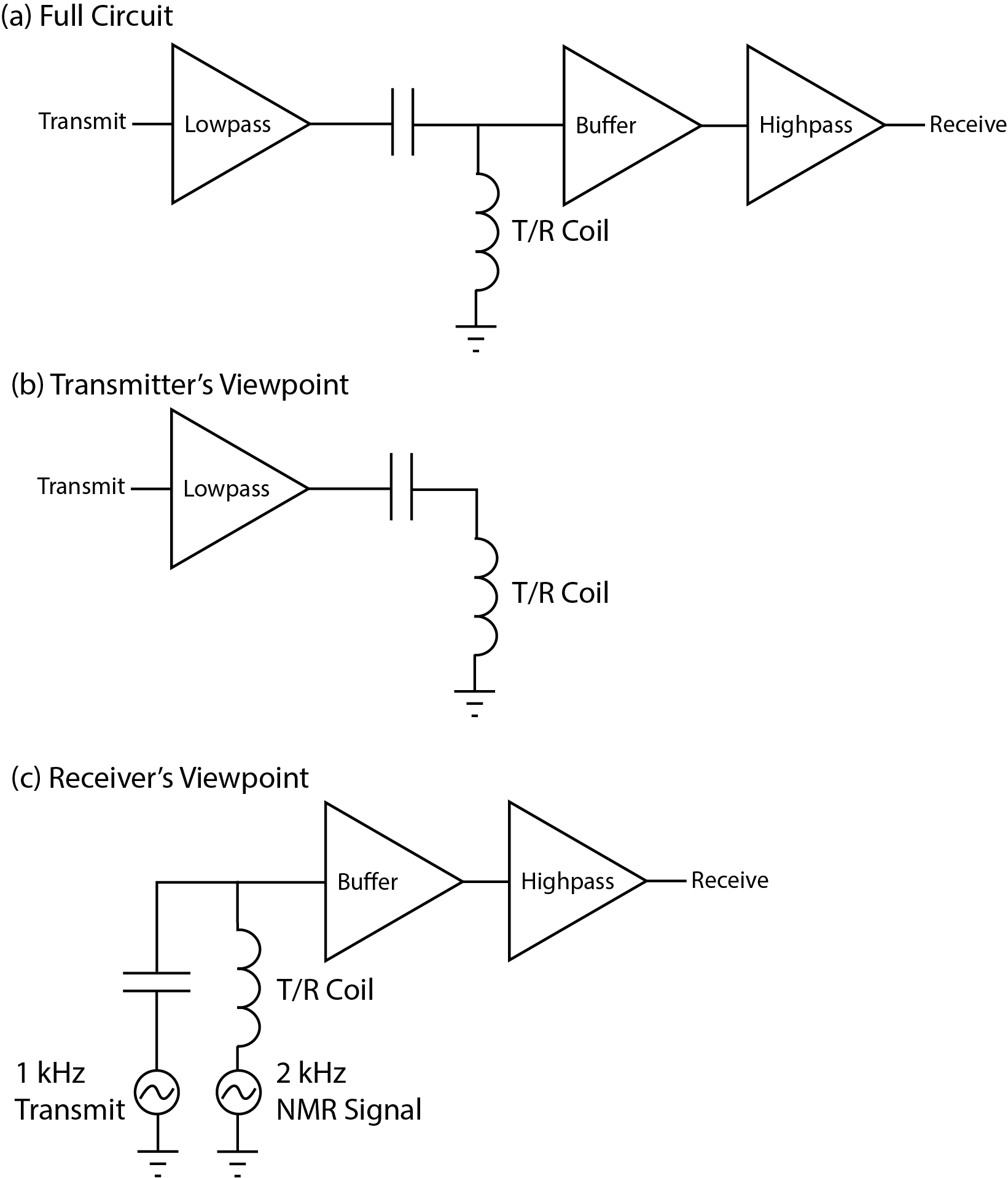
A homebuilt prepolarized Earth’s field spectrometer was made following a combination of techniques from Michal7 and Trevelyan8. For pulse programming, a Matlab script via an ASIO interface was used to control a RME ADI-2 Pro FS AD/DA converter (RME, Germany) synchronized to an Analog Discovery 2 (Digilent, USA). The RME ADI-2 Pro FS was used to transmit pulses and acquire data, while the Analog Discovery 2 was used to provide control signals for various relays related to prepolarization. The prepolarization strength was estimated to be about 25 mT and was turned on for 6 seconds at a time. Figure 2 shows a block diagram of the overall system.To implement simultaneous two-photon excitation and reception, active lowpass and highpass filters were designed. Figure 3 shows schematics and simulations for the filters. The lowpass filter was connected to the output of the RME ADI-2 Pro FS to filter out noise and harmonic distortion in the transmit waveform. The output of the lowpass filter was coupled to the transmit/receive coil with a capacitor. The voltage across the transmit/receive coil was connected to a unity gain buffer, which was then connected to a highpass filter to filter out the transmit frequency and keep the Larmor-frequency signal. The output of the highpass filter was connected to the input of the RME ADI-2 Pro FS. Figure 4 shows these more detailed connections.
Results
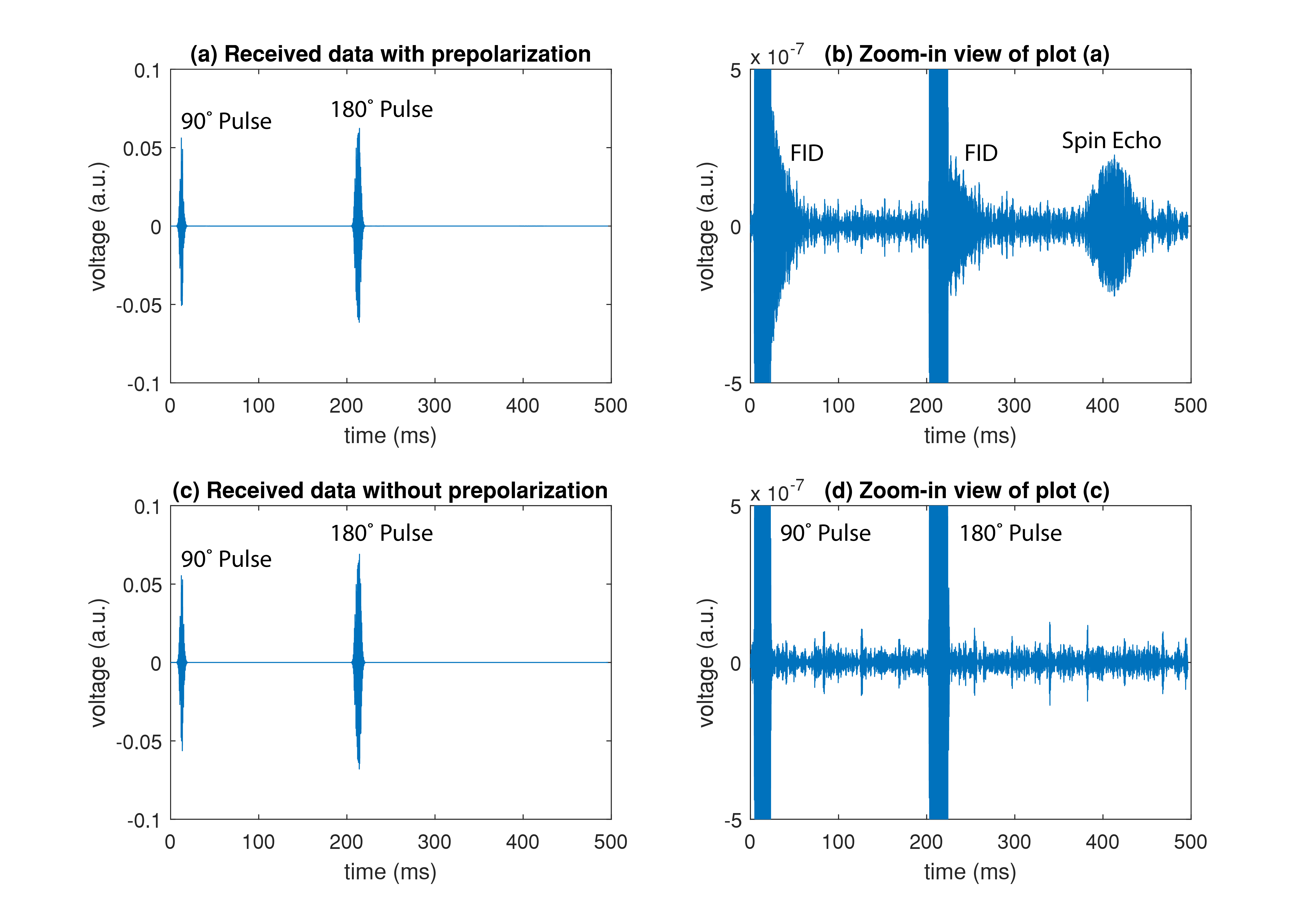
Figure 5 shows the result of a spin echo sequence with and without the prepolarization power supply turned on, thus giving results with and without NMR signal. When the prepolarization is used, FIDs can be seen directly after the 90- and 180-degree pulses. Without prepolarization, only the second harmonic distortion from the excitation pulses is observed.Discussion and Conclusions
We have realized zero-dead-time NMR at the Earth’s field by separating the transmit and receive frequencies and using filters to isolate them. These filters were implemented using op amps, resistors, and capacitors instead of inductors and capacitors because inductors for this frequency range were found to be bulky, have low Q factors, and easily pick up external interference signals. Although op amps and resistors introduce noise into the circuit, this was mitigated by proper choice of op amps and low resistance values. Unfortunately, the circuit still contained second-harmonic distortion that made us unable to completely isolate resonance signal from transmit signal. The cause of this will be investigated in future work. Improving the SNR of the basic Earth-field NMR setup by shimming the $$$B_{0}$$$ field and moving it out of a noisy apartment closet (a byproduct of the COVID-19 pandemic) may also help with this.In the future, we would like to apply this technique to hyperpolarized studies such as with hyperpolarized Carbon-13. Along with long liquid relaxation times and high potential field homogeneity at low field, zero dead time/simultaneous transmit and receive could increase SNR and potentially reveal any ultrashort $$$T_2$$$ signals.
Acknowledgements
Thanks to Kevin Gao of UC Berkeley for assistance with building the base Earth's field spectrometer.References
1. Kraus R, Espy M, Magnelind P, Volegov P. Ultra-Low Field Nuclear Magnetic Resonance: A New MRI Regime. 1 edition. Oxford University Press; 2014.
2. Yablonskiy DA, Sukstanskii AL, Ackerman JJH. Image artifacts in very low magnetic field MRI: The role of concomitant gradients. Journal of Magnetic Resonance. 2005;174(2):279-286. doi:10.1016/j.jmr.2005.02.016
3. Hayden ME, Bidinosti CP, Chapple EM. Specific absorption rates and signal-to-noise ratio limitations for MRI in very-low magnetic fields. Concepts in Magnetic Resonance Part A. 2012;40A(6):281-294. doi:10.1002/cmr.a.21247
4. Michal CA. Nuclear magnetic resonance noise spectroscopy using two-photon excitation. The Journal of Chemical Physics. 2003;118(8):3451-3454. doi:10.1063/1.1553758
5. Han V, Liu C. Multiphoton magnetic resonance in imaging: A classical description and implementation. Magnetic Resonance in Medicine. 2020;84(3):1184-1197. doi:https://doi.org/10.1002/mrm.28186
6. Zhen JZ, O’Neill KT, Fridjonsson EO, Stanwix PL, Johns ML. A resistive Q-switch for low-field NMR systems. Journal of Magnetic Resonance. 2018;287:33-40. doi:10.1016/j.jmr.2017.12.006
7. Michal CA. A low-cost spectrometer for NMR measurements in the Earth’s magnetic field. Meas Sci Technol. 2010;21(10):105902. doi:10.1088/0957-0233/21/10/105902
8. Trevelyan. MRI and NMR Spectroscopy in the Earth’s Field: Building a Low-Cost NMR Spectrometer for Hobby Science and Teaching. Independently Published; 2019.
Figures