4030
In vivo human imaging on a 47.5mT open MRI system with active Electromagnetic Interference (EMI) mitigation using an electrode1Vanderbilt University Institute of imaging science, Nashville, TN, United States, 2Department of Biomedical Engineering, Vanderbilt University, Nashville, TN, United States, 3Harvard Medical School, Boston, MA, United States, 4Dept. of Radiology, Massachusetts General Hospital, Athinoula A Martinos Center for Biomedical Imaging, Boston, MA, United States, 5Harvard-MIT Division of Health Sciences and Technology, Cambridge, MA, United States, 6Department of Electrical Engineering, Vanderbilt University, Nashville, TN, United States, 7Department of Radiology, Vanderbilt University, Nashville, TN, United States
Synopsis
Low-field MRI scanners can operate outside MR safe rooms, but their image quality is adversely affected due to the presence of electromagnetic interference signals which can severely obscure the images. We demonstrate a generalized dynamic model that can handle time-varying external interference sources by using simultaneously acquired data from multiple EMI detectors - specifically from an electrode, traditional RF pick up coils and the primary MR coil - in-vivo, in real world EMI settings on a 47.5mT permanent magnet open MRI system.
Introduction
Electromagnetic Interference (EMI) contaminates MR signals and decreases the diagnostic quality of the image. These nuisance signals are detected the same way as the spins, i.e., through Faraday detection with primary MR imaging coils. Conventional MRI scanners use RF shielded enclosures to reduce EMI. However, the necessity of an RF shielded room precludes their use in a POC setting. To fully utilize the potential of a low-field MRI, alternative approaches to EMI suppression are needed. The use of external detectors (pick up coils) for image noise reduction in MRI has previously been described using calibration data to calculate a transfer function [1,2,3]. The weakness of transfer function approaches is the increase in scan time and/or the inability to detect intermittent or time-varying data. To address this, we propose to generate a dynamic EMI correction using only the data that is acquired simultaneously during the scan from EMI detectors external to the imaging volume and the primary MR coil. Additionally, we use electrodes as EMI detectors which may pick up EMI that is coupled into the primary MR coil by the subject directly. This EMI correction model is comprised of a spatio-temporal kernel that detects the EMI which is correlated to the EMI received by the primary imaging coil and removes it in postprocessing from the primary MR data.Methods
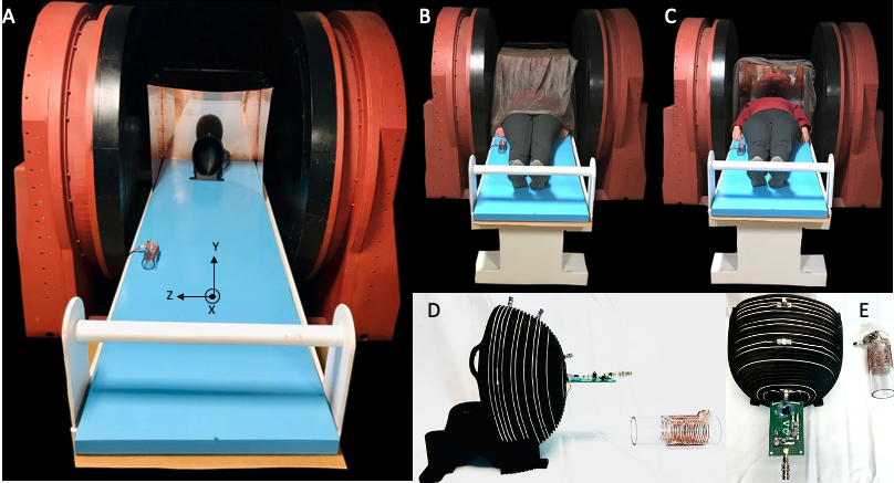
We implemented the proposed EMI mitigation methodology in an open 47.5mT scanner (Sigwa 48.7mT, Boston NMR, Boston, MA) for human brain imaging shown in figure 1a. Due to the open nature of the system, passive shielding around the scanner is a challenge. The primary MR coils are placed in a head-sized copper box, and the subject is draped with silver nylon and copper mesh in an effort to reduce EMI interference. This shielding reduces EMI insufficiently for in vivo human imaging experiments. This method can address the significant interference that remains. Our method uses two external EMI detectors placed outside the imaging coil. The first is a traditional pick-up coil with 10 evenly spaced turns on an acrylic former (OD = 5cm) as shown in Figure 1d and 1e. It is tuned to 2.07MHz to mimic the frequency response of the primary coil with a similar bandwidth. The second detector is an electrode (EverOne ECG Monitoring) attached to the subject’s wrist which may detect EMI that is coupled to the imaging coil via the subject. Both EMI detectors were connected to 50-ohm 70 dB gain pre-amplifiers (MITEQ P/N 1647). An unevenly wound 12 turn spiral Tx/Rx helmet coil [4,5] with a BW of 20KHz was used for imaging as shown in Figure 1d and 1e. Additionally, this imaging coil was connected to a 50-ohm 70 dB gain pre-amplifier (MITEQ P/N 1583 10057). The EMI mitigation algorithm is based on the assumption that the primary coil data is the combination of EMI (E’) and the true image (P’):$$P(k_x,k_y )=E'(k_x,k_y )+ P'(k_x,k_y )$$
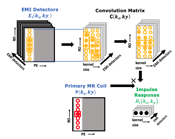
Each of the N external probes’ data along the readout and phase encoding directions $$$E_i (k_x,k_y )$$$ is related to the EMI observed by the primary coil EMI $$$E'(k_x,k_y )$$$ through convolution with impulse response functions $$$H_i (k_x,k_y )$$$ as shown in Figure 2:
$$E'(k_x,k_y )=∑_{(i=1)}^{N}E_i (k_x,k_y )*H_i (k_x,k_y )$$
The transfer function can be found by solving a linear system :
$$H_N (k_x,k_y )=E_N (k_x,k_y )^† P(k_x,k_y )$$
Once the $$$H_i (k_x,k_y )$$$ are calculated, $$$E'≈EH$$$ can be directly subtracted from the primary coil data $$$P(k_x,k_y )$$$ . Similar to GRAPPA, we assume a $$$(K_x,K_y )$$$ limited support window for each response function, i.e., $$$H_i (k_x,k_y )=0,|k_x |>K_x or |k_y |>K_y$$$.This limited support window is determined by obtaining the transfer function $$$H_i (k_x,k_y )$$$ for each phase encode line and thresholding the autocorrelation of the transfer function. This thresholding determines binning of phase encodes so that time-localized transfer functions can be fit.
To evaluate the method, a 3D RARE sequence with 23 PE’s in X and 67 PEs in Y was used to collect images of a human subject, with approval of the Vanderbilt University IRB.
Results
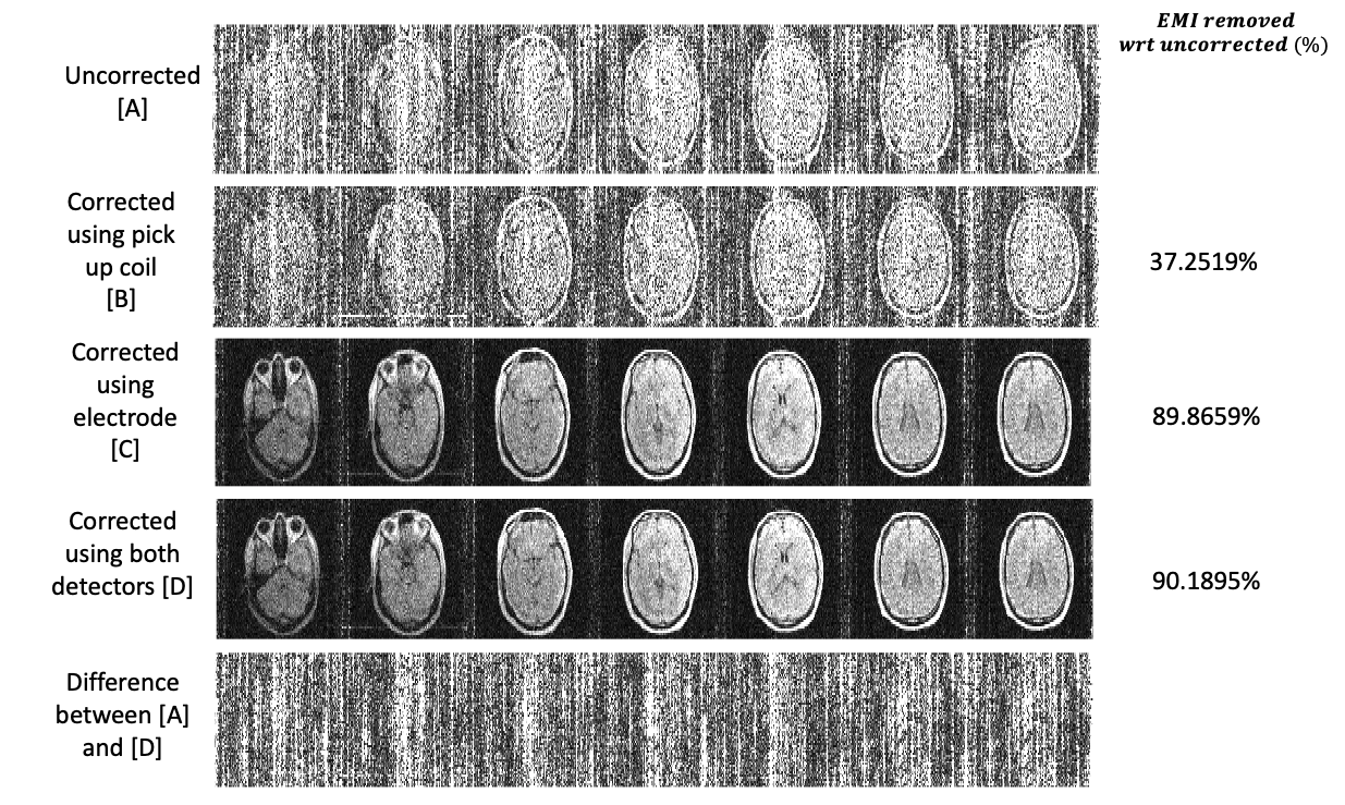
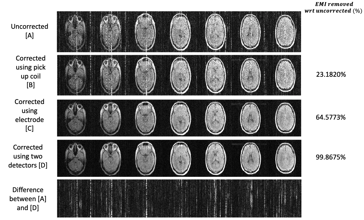
Figure 3 shows PD images in a human subject EMI corrected using each EMI detector and both detectors combined in the setup shown in Figure 1b with the copper sheet shielding. Figure 4 shows similar images but in an open configuration as shown in Figure 1c. All images were evaluated using the equation:$$ EMI_{removed}=|\frac{SD _{uncorrected}- SD _{corrected}}{SD _{uncorrected}}| \times 100 \%$$
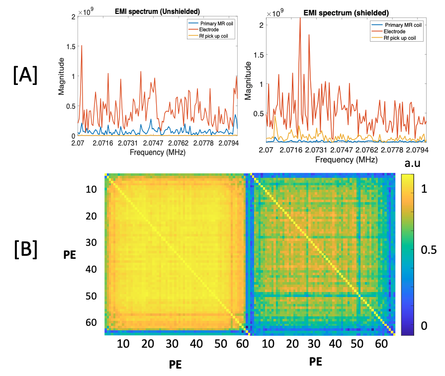
Figure 5a shows the EMI spectrum seen by the EMI detectors and the primary MR coil. Figure 5b shows the correlation matrix between impulse response functions for each PE line used to determine the binning of PE for time-localized transfer functions.
Discussion
We demonstrate a dynamic EMI mitigation method capable of handling time-varying EMI in vivo, in real world EMI settings using an electrode and a pickup coil. In future work, we intend to show correction for multiple contrast images.Acknowledgements
Funding support from R01 EB030414, NIH NIBIB R01EB018976 and 5T32EB1680References
1. Rearick Todd et al., “Noise Suppression methods and apparatus”. Patent no. WO2016037028. 2017.
2. Patz.S, Hrovat.M & Butler. P.J. “Systems and methods for portable magnetic resonance measurements of lung properties”. Patent no. WO2013016639A1. 2013.
3. Srinivas, S. A., Cooley, C. Z., Stockmann, J. P., McDaniel, P. C. & Wald, L. L. Retrospective Electromagnetic Interference Mitigation in a Portable Low Field MRI System. Proc. 28th Annu. Meet. ISMRM. 2020 (2020).
4. C. LaPierre, M. Sarracanie, D. E. J. Waddington, M. S. Rosen, and L. L. Wald, “A single channel spiral volume coil for in vivo imaging of the whole human brain at 6.5 mT,” Proc. 23rd Annu. Meet. ISMRM, Toronto, 2015, p. 1793, 2015.
5. Cooley, C.Z., McDaniel, P.C., Stockmann, J.P. et al. A portable scanner for magnetic resonance imaging of the brain. Nat Biomed Eng (2020). https://doi.org/10.1038/s41551-020-00641-5
Figures