4019
Promising results using synthetic CT for 2D and 3D patient positioning in head and neck radiotherapy1Department of Radiation Physics, Institute of Clinical Sciences, Sahlgrenska Academy, University of Gothenburg, Gothenburg, Sweden, 2Department of Medical Physics and Biomedical Engineering, Sahlgrenska University Hospital, Gothenburg, Sweden, 3Department of Oncology and Radiotherapy, Institute of Clinical Sciences, Sahlgrenska Academy, University of Gothenburg, Gothenburg, Sweden
Synopsis
In an MRI-only radiotherapy workflow, in addition to enabling absorbed dose calculation the generated synthetic CT (sCT) must also be valid for patient positioning at treatment course. To evaluate MRI-only patient positioning for head and neck cancer patients, fourteen 3D cone beam CTs were retrospectively registered to CT and sCT. Further, original Digital Reconstructed radiographs originating from the CT and synthetic Digital Reconstructed radiographs originating from the sCT, were retrospectively registered to orthogonal projections. The small mean difference between the registrations showed that sCT could replace the CT for both 3D and 2D head and neck radiotherapy patient positioning.
Introduction
In a traditional external radiotherapy workflow, CT data is used for absorbed dose calculation and delineation of target and organs at risk (OAR). In addition, CT data are used for patient positioning by registration of daily orthogonal 2D projections to Digital Reconstructed Radiographs (DRR) originating from CT, or registration of a 3D cone beam CT (CBCT) directly to the CT data. MRI, with its superior soft tissue contrast, can be incorporated into the radiotherapy workflow via a co-registration to the CT data, and contributes with a more consistent estimation of tumor volumes1,2. Lately, interest have been directed towards MRI-only radiotherapy workflows, i.e. a radiotherapy workflow that uses MRI as the only imaging modality. Since the MRI does not provide the electron densities necessary for absorbed dose calculation and cannot be directly reconstructed to DRRs with the same contrast as the CT data, additional steps are required. These generally includes a conversion of the MRI data to synthetic CT data (sCT) using e.g. machine learning. In an MRI-only workflow, sCT and synthetic DRR (sDRR) originating from the sCT data replaces the original CT and DRR data. The accuracy of sCT based absorbed dose calculations has previously been evaluated for various sCT generation methods and treatment sites3,4, however the impact on the patient positioning has not yet been thoroughly investigated5 and to our knowledge never in the head and neck (H&N) region. The aim of this study was to evaluate the use of sCT and sDRR for patient positioning in an MRI-only H&N radiotherapy workflow.Methods
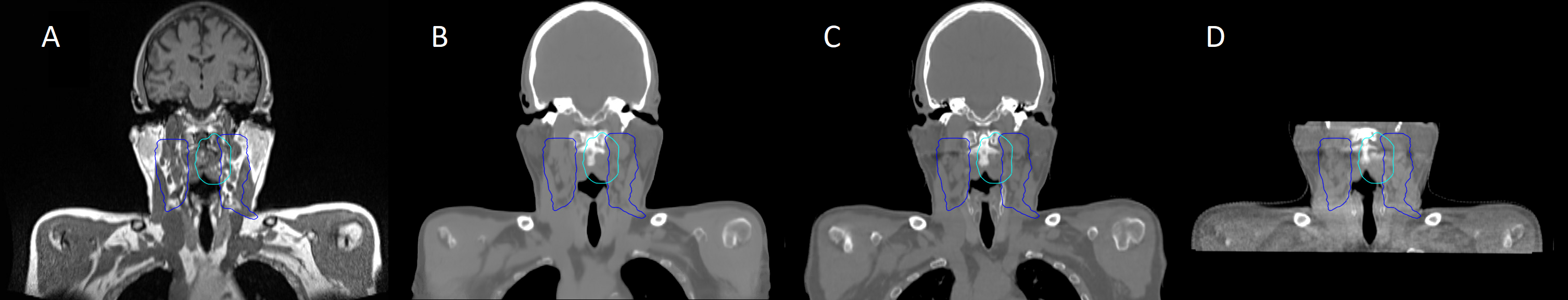
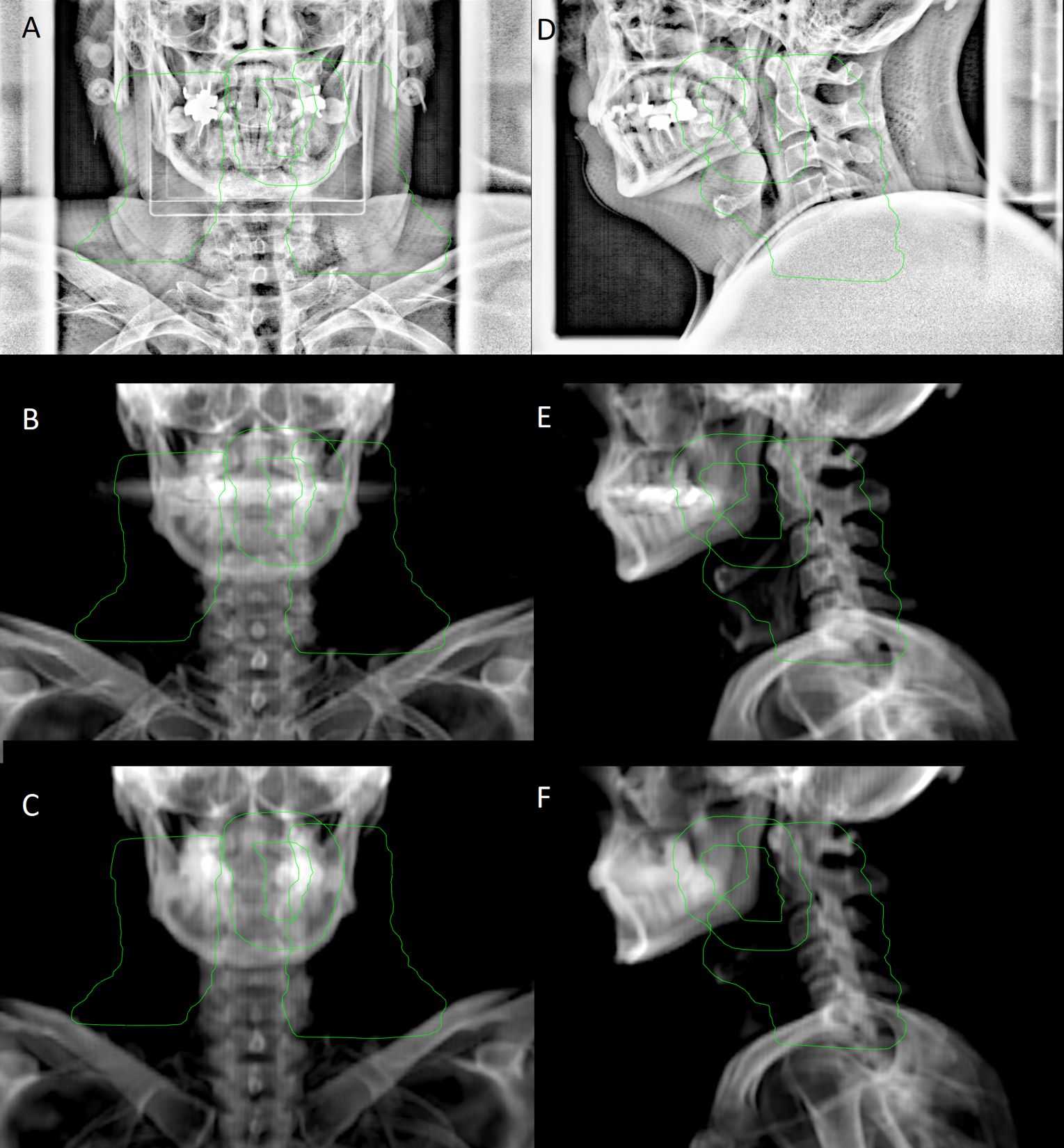
In this study, 14 data sets with MRI, sCT, CT, CBCT (figure 1) and orthogonal projections (figure 2) in the H&N region were used. A T1 weighted Dixon Vibe (3D spoiled GRE) acquisition was used for generation of sCT data (MRI Planner software, Spectronic Medical AB). The original CT was deformably pre-registered to the MRI (Elastix, MICE Toolkit) to mitigate differences due to inconsistent positioning of the patient during the two scanning sessions and/or anatomical movement in the body. To validate the physical behavior of the deformation, the determinant of the Jacobian of the deformation field was calculated within the body contour of the deformed CT (dCT) data.For positioning using 3D data, the CBCT was registered to the dCT and sCT in six degrees of freedom with a rigid auto-registration algorithm and a threshold of 200-1700 HU (Eclipse Image Registration, Varian Medical Systems).
For positioning using 2D data, the deformed DRRs (dDRR) and sDRRs were retrospectively and manually registered to orthogonal projections in five degrees of freedom by six blinded observers (3 physicists, 3 radiotherapy technologists), resulting in a total of 168 registrations (Eclipse Offline Review, Varian Medical Systems). None of the observers were informed of the type of DRRs that were registered to the orthogonal projections.
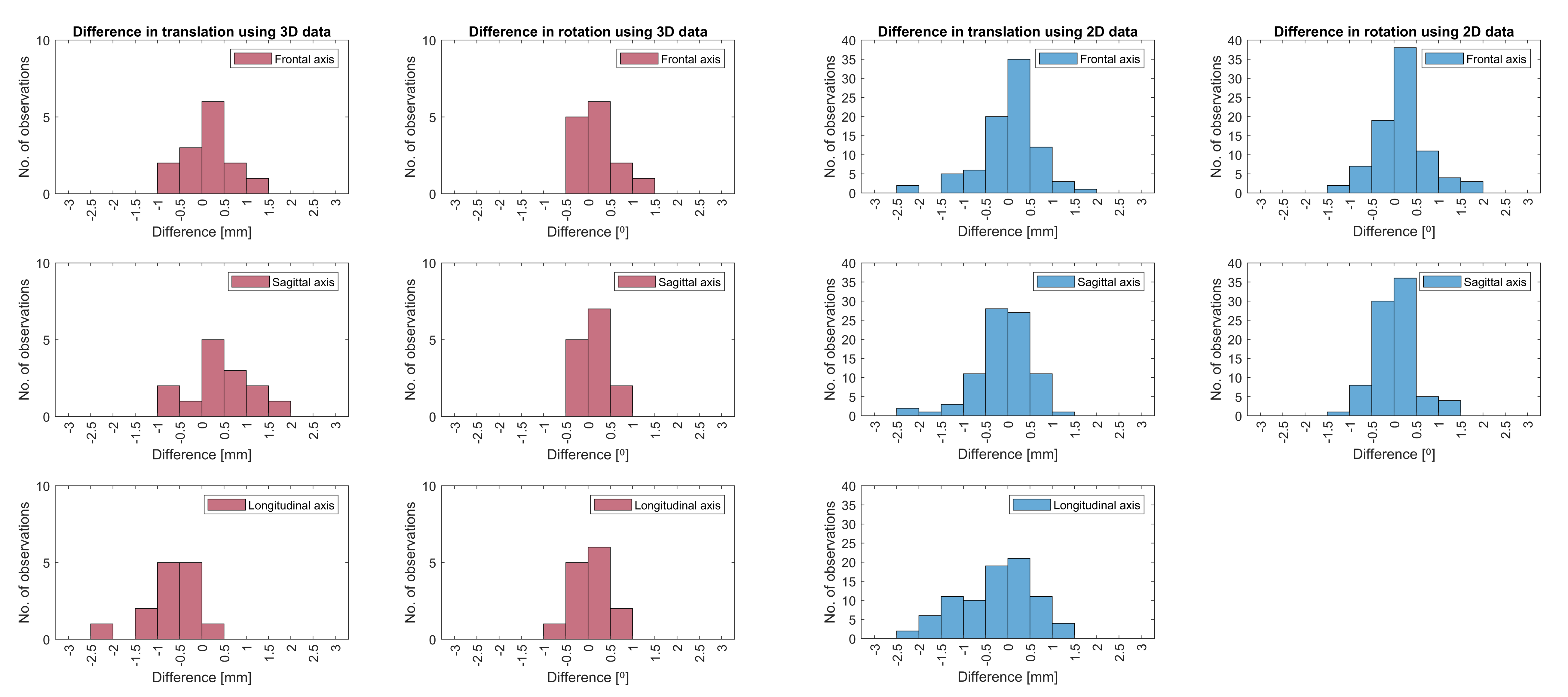
The difference between patient positioning in all directions (frontal, longitudinal and sagittal axis, and rotation around these axis) were evaluated for dCT and sCT, as well as for dDRR and sDRR.
Results
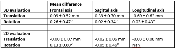
All determinants of the Jacobin of the deformation fields were >0 within the body contours for thirteen of the dCT data sets.The differences in translation and rotation for 3D and 2D patient positioning in all directions are presented in figure 3. The mean difference (± 1sd) for 3D and 2D patient positioning is shown in table 1.
Discussion
The small mean differences found indicated that both sCT and sDRRs contributed with an overall comparable patient positioning as for CT and DRRs. Similar results have previously been presented for prostate and brain5.Larger inter-observer variations were seen for some cases. These deviations could have arisen from different strategies of using translation and rotation when registering the images. The different registration strategies could provide relatively large differences in mm or degree between observers, but the outcome of patient positioning would be similar. These cases however need to be more deeply analyzed.
The pre-registration used to mitigate differences between CT and MRI data is a critical step in this study, since an insufficient pre-registration would affect the results in the patient positioning evaluation. The quality of the pre-registration was estimated by calculating the determinant of the Jacobian of the deformation field, where a determinant >1 would indicate expansion and a determinant between 0 and 1 would indicate a contraction of the voxel. One of the 14 dCT data set had voxels <0 within the body contour which would indicate a physically unrealistic deformation. The cause was identified to be the skin on the back which had been folded double at the MRI acquisition causing a non-invertible deformation. To further investigate this, an evaluation of the anatomical correspondence between the dCT and MRI using anatomical landmarks will be added to the evaluation of the Jacobian of the deformation field.
Conclusion
The study showed that sCT could replace the CT for both 3D and 2D patient positioning and are therefore promising to be utilized in MRI-only head and neck radiotherapy workflow.Acknowledgements
No acknowledgement found.References
1. Coen R, Ronald K, Frank AP, et al. The potential impact of CT-MRI matching on tumor volume delineation in advanced head and neck cancer. International Journal of Radiation Oncology Biology Physics. 1997;39:841-848.
2. Anuradha T, Nicola C, Heiko S, et al. Target volume delineation in oropharyngeal cancer: Impact of PET, MRI, and physical examination. International Journal of Radiation Oncology Biology Physics. 2012;83:220-227.
3. Anna MD, Jelmer MW, Matteo M, et al. MR-Only Brain Radiation Therapy: Dosimetric Evaluation of Synthetic CTs Generated by a Dilated Convolutional Neural Network. International Journal of Radiation Oncology Biology Physics. 2018;102:801-812.
4. Neelam T, Sandra F, Jing Z, et al. Dosimetric and workflow evaluation of first commercial synthetic CT software for clinical use in pelvis. Physics in Medicine and Biology. 2017;62:2961-2975.
5. Amir MO, Peter BG, Carri KG-H. MRI-only treatment planning: Benefits and challenges. Physics in Medicine and Biology. 2018;63.
Figures