4013
Comparison of birdcage resonator designs for clinical MR-guided radiotherapy1Medical Physics in Radiology, German Cancer Research Center (DKFZ), Heidelberg, Germany, 2Radiation Oncology, University Hospital, Heidelberg, Germany, 3Faculty of Medicine, Heidelberg University, Heidelberg, Germany
Synopsis
Electromagnetic field simulations were performed at 0.345T and 1.5T to find an advantageous RF coil design for typical scanners in MR-guided therapy. Hence, different birdcage coil designs were characterized and compared with one another with respect to their corresponding transmit and receive field characteristics.
Purpose
Recently, MR-guided radiotherapy (MRgRT) has gained popularity as an alternative to conventional radiotherapy, which is performed either without image guidance or with image guidance based on ionizing radiation [1]. The benefits of MR guidance include enhanced soft tissue contrast as well as no additional dose exposure caused by imaging. The key advantage of MRgRT lies in particular in adaptive cancer therapy with inter-fractional treatment plan corrections and real-time radiation gating. To potentially further decrease the dose to the surrounding, healthy tissue, MR imaging can be combined with particle therapy [2]. A possible realization would be a hybrid MR-ion beam system. However, this configuration puts strict constraints on the RF coil of the MR system, which would require large spatial openings for the particle beam while maintaining a homogeneous RF-field over a large field of view (FOV). This is particularly relevant in the direction of the particle beam, where field uniformity ensures reliable contrast between different tissues. In this work, electromagnetic field simulations were performed for MR scanners with an axial magnetic field of 0.345T and 1.5T to find an advantageous RF coil design for clinical scanners in MRgRT. Birdcage coil designs [3][4] were investigated due to the requirement of increased homogeneity in transmit and receive fields.Methods
Coil: In addition to the conditions mentioned above, the RF coil should remain fixed with respect to the patient to ensure that the particle beam does not hit the RF coil at any time. Hence, a 4-leg birdcage configuration that can be attached relatively easily to a static coil housing was deemed suitable for this purpose. The proposed birdcage body coil design with a length of 30cm and a diameter of 60cm consists of a copper conductor of 100µm thickness. With this geometry, almost the complete torso of a patient can be imaged without occupying too much space in the scanner bore. Furthermore, this coil can be used in scanners without an internal transmit coil, as it provides the option of both receiving and transmitting RF-signals in quadrature mode. Scanner: Commercially available MR-scanners for MR-guided therapy currently possess a magnetic field strength of either 0.345T [5] or 1.5T [6]. Thus, the resulting Larmor frequencies for hydrogen correspond to f=14.7MHz and f=63.9MHz. Despite major simplification of the scanner design for the simulations, standard dimensions of critical parts such as the bore with a 70cm diameter and the gradient coil as boundary condition were taken from commercially available scanners. Simulation: The simulation was performed in CST Studio Suite 2019 [7] with a frequency range from 0 to 150MHz. The total number of mesh cells in the simulation model is 16-17 million, whereby the resolution inside the RF coil was enhanced and a cell size of 2mm was allocated in close proximity to the signal ports. To simplify the calculation, all metals were assumed to be perfectly conducting whereas acrylic glass and vacuum were chosen as insulating materials. The 3D-model is shown in Fig. 1. The gradient coil, which acts as an RF shield, was implemented in the simulation model. Acrylic glass was used for all considered insulators, namely the bore liner, the table, the housing of the coil and the phantom. The dielectric properties were then extrapolated in CST Studio Suite from ɛr=2.8 and tan(δ)=0.02 (1MHz) for the required frequencies. For the phantom, a mixture with ɛr=55.54 and σ=0.4252$$$\frac{S}{m}$$$ for all frequencies was simulated. Field homogeneity was investigated in a region of interest (ROI) with the dimensions of 240cm × 170cm × 260cm. Standard MR images can be calculated from the transmit (B1+) and receive fields (B1-) via $$$S(\vec{x})=sin(\gamma\cdot B_{1,90^{\circ}}^+(\vec{x})\cdot t_P)\cdot B_1^-(\vec{x})$$$.Results
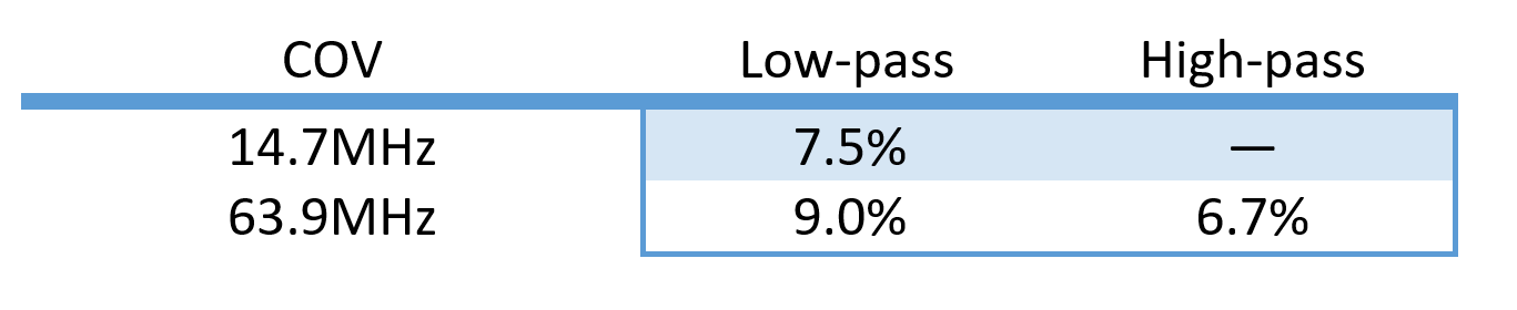
The homogeneity in transmit and receive field distributions was examined in both a phantom and a human voxel model for a low-pass and a high-pass birdcage configuration. As reported in the literature, the large-size high-pass birdcage coil could not be tuned to the Larmor frequency at 0.345T of 14.7MHz [8]. The simulated low-pass birdcage configuration at 14.7MHz and at 63.9MHz and the high-pass birdcage at 63.9MHz show good field characteristics with homogeneous field distributions and uniform MR imaging capabilities (Fig. 2-4). This is also confirmed by the low value of the determined coefficient of variation (COV=standard deviation/mean) (shown in Fig. 5.), as low values correspond to small variation of the fields. Slight field asymmetries are present in the B1+ and B1- field distributions.Discussion and Conclusion
The presented simulation results demonstrate that a 4-leg birdcage is a promising design for the application in MRgRT. Depending on the magnetic field strength of the scanner in use, a high-pass birdcage might be feasible (e.g. for 63.9MHz), however a low-pass configuration seems more appropriate in the frequency range of the considered MR-scanners (14.7MHz and 63.9MHz). Slight inhomogeneities and asymmetries of B1+ and B1- field distributions for large resonators were already reported in the literature [9][10]. In this work, simulations were performed for a closed bore liner without an opening for radiation beams. A more sophisticated simulation with a different magnet configuration with a central opening for radiation beams would provide results closer to the expected design.Acknowledgements
The project received financial support from the German Federal Ministry of Education and Research (BMBF, ARTEMIS project WP8, funding reference 13GW0436B).References
[1] Pollard J. M. et al., "The future of
image-guided radiotherapy will be MR guided", The British
Institute of Radiology (2017)
[2] Hoffmann A. et al., "MR-guided
proton therapy: a review and a preview", Radiation Oncology 15
(2020); 1-13
[3] Tropp J., "The theory of the bird-cage resonator", Journal of Magnetic
Resonance (1989); 82:51-62
[4] Hayes C. E. et al., "An efficient, highly
homogeneous radiofrequency coil for whole-body NMR imaging at 1.5T", Journal of Magnetic Resonance
(1985); 63:622-628
[5] Klüter S., "Technical design and
concept of a 0.35 T MR-Linac", Clinical and translational radiation oncology (2019); 18:98-101
[6] Raaymakers B. W. et al., "First patients treated with a 1.5 T
MRI-Linac: clinical proof of concept of a high-precision, high-field MRI guided
radiotherapy treatment" Physics in Medicine & Biology (2017); 54.12
(2009): N229
[7] "CST Studio Suite 2019",
Dassault Systèmes, Vélizy-Villacoublay, France
[8] Mispelter J., "NMR Probeheads for biophysical
and biomedical experiments”, Imperial College Press (2006), p. 390
[9] Manushka V. V. et al., "Dependence of B1+
and B1- field patterns of surface coils on the electrical
properties of the sample and the MR operating frequency",
Concepts in Magnetic Resonance Part B (2016); 46:25-40
[10] Martijn A. C. et al., "Multiparametric imaging with
heterogeneous radiofrequency fields", Nature Communications (2016); 7:12445
Figures