4010
Attenuation of the dark band artifact in MR-guided focused ultrasound using an ultra-flexible high-sensitivity head coil1Department of Radiology, Weill Cornell Medicine, New York, NY, United States, 2MR Engineering, GE Healthcare, Aurora, OH, United States, 3Department of Neurological Surgery, Weill Cornell Medicine, New york, NY, United States
Synopsis
Transcranial magnetic resonance guided focused ultrasound (MRgFUS) has shown dramatic success in the treatment of various neurodegenerative diseases. However, black band artifacts arise in MR images due to the high-permittivity water bath and the metallically lined helmet-shaped transducer together with the vendor-installed body coil. In this work, we present electromagnetic simulations of a very thin, flexible, and acoustic transparent head coil design (FUS-Flex). Simulations show a signal-to-noise-ratio (SNR) increase of 3.5× and 5× compared to a body coil with and without the transducer, respectively, and an attenuation of the black band artifact in the regions of interest.
Introduction
Transcranial magnetic resonance guided focused ultrasound (MRgFUS) has shown dramatic success in the treatment of a growing range of neurodegenerative diseases, such as essential and parkinsonian tremors and early-stage brain tumors1-4. However, very poor image quality and thus poor focal precision is observed because the presence of the transducer helmet inhibits the use of a conventional head coil and necessitates the vendor-installed body coil. Black band artifacts arise in the MR images due to the presence of a high-permittivity water bath in between the coil and the head that causes significant shortening of the wavelength of the radiofrequency (RF) signal and therefore strong RF field (B1) inhomogeneities resulting in image shading5. Further, the transducer exhibits an internal metal surface acting as a reflective surface, causing B1 field cancellations and the typical dark band observed in MRgFUS-related brain images6. This work proposes a high sensitivity, ultra-flexible7, and ultra-thin 8-channel head (FUS-Flex) coil located directly on the surface of the head for maximized signal-to-noise-ratio (SNR) and avoidance of B1 inhomogeneity/cancellation effects.Methods
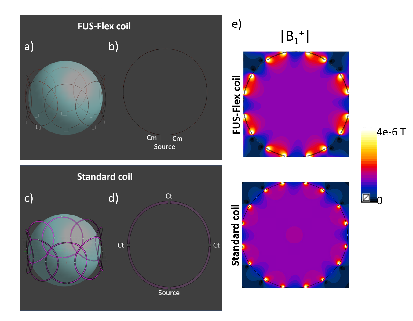
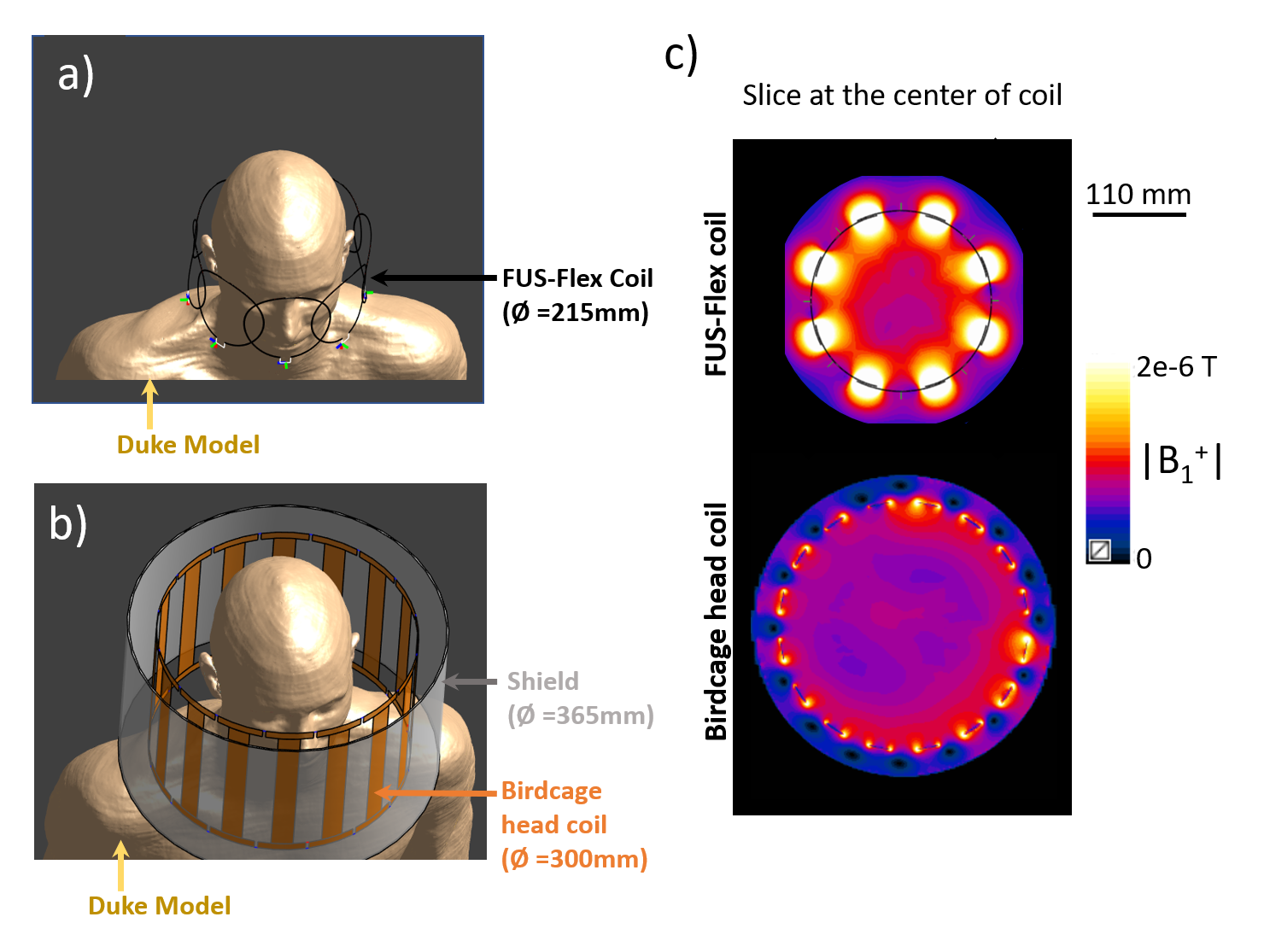
The FUS-Flex coil consists of an 8-channel array using receive architecture inspired by the highly flexible and very thin (around 1mm-diameter) AIR™ Coil technology8-11 and is designed to be placed conformally and close-fittingly around the circumference of the patient’s head. Electromagnetic simulations were performed using Sim4Life12 to maximize the SNR of the 8-channel receive array using an element diameter of 110 mm (Figure 1). The FUS-Flex coil was placed around a 180 mm-diameter spherical phantom (σ = 0.55 S/m and εr = 78) and compared to a conventional same diameter circular copper coil to confirm proper functionality.Conventional performance (non-MRgFUS) : For a realistic in silico scenario, a body model, Duke13 was used. First, to quantify non-MRgFUS performance increases, the FUS-Flex coil was compared to a 16-leg conventional birdcage head coil (diameter: 300 mm; length: 200 mm) without the transducer (Figure 2). Additionally, the FUS-Flex coil was compared to a 16-leg body coil (diameter: 620 mm; length: 570 mm) (Figure 3).
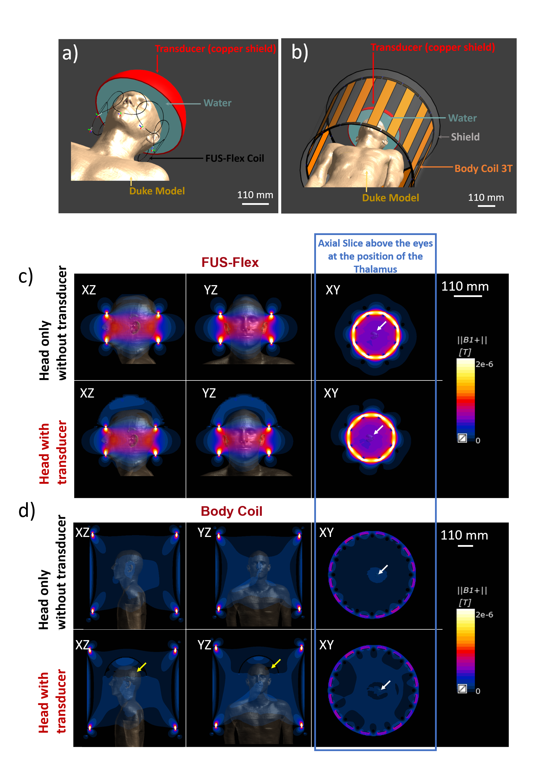
MRgFUS performance : Then, the transducer, modeled using a semispherical water-filled copper-coated geometry, was placed over Duke’s head to simulate the influence of the transducer on the B1 field distribution (Figure 3). Simulations were performed comparing the proposed FUS-Flex coil to the 16-leg body coil in order to quantify imaging performance increases with the transducer.
Results
The B1+ sensitivity maps of the FUS-Flex and standard coils in the spherical phantom (Figure 1) are very similar and confirm functional operation of the very thin FUS-Flex coil. Figure 3c shows the simulated B1 maps for the FUS-Flex and body coil with and without the presence of the transducer, denoting an SNR improvement of 3.5× and 5× with and without the transducer, respectively. As expected from literature 6, RF signal reflection from the copper-coated transducer cancels the field and causes a typical dark band in MRgFUS images in the body coil along with a significant reduction in B1 magnitude. The location of the FUS-Flex coil is chosen to provide 2.6-fold increased SNR in the direct region of the dark band, and results show that, in fact, the band successfully recedes to a region outside the brain with a very small portion at the very upper limit of the head, which is above the thalamus ROI (XZ-plane in Figure 3c), while B1 levels are maintained compared to those without the transducer setup. This suggests feasibility to produce a significant increase of image quality over the body coil. The FUS-Flex coil exhibits B1+ and thus SNR increases by a factor of 1.4 without the presence of the transducer are compared to a standard birdcage head coil (Figure 2). It should be noted that for these simulations, the FUS-Flex coil array was considered to be of circular shape (diameter of 215 mm) which is not the case in a real exam because the coil is very flexible and perfectly conforms to the shape of the head with maximized SNR. First in vivo results are reported in reference.14Discussion and conclusions
Simulations showed universal SNR improvement compared to a head coil (1.4×) and a body coil (3.5× with transducer, 5× without transducer) at the position of the thalamus and (4.5× with transducer, 8× without transducer) at the center of the coil. In addition, the simulated B1 field showed a 2.6-fold increase of the signal in the black band. These first simulated results along with the in vivo results in ref 14 suggest that the FUS-Flex coil could replace the body coil and even the standard head coil in non-MRgFUS settings. For the MRgFUS surgery this could mean improved focal precision, as well as the availability of real-time intraprocedural anatomical imaging and 3D thermometry mapping.Acknowledgements
This work was supported by the National Institutes of Health (NIH K99/R00 4R00EB024341-03) and GE Healthcare.References
1. Levi Chazen J, Stradford T, Kaplitt MG. Cranial MR-guided Focused Ultrasound for Essential Tremor. Clinical Neuroradiology. 2019;29(2):351-357.
2. Lipsman N, Meng Y, Bethune AJ, et al. Blood–brain barrier opening in Alzheimer’s disease using MR-guided focused ultrasound. Nat Commun. 2018;9(1).
3. Lamsam L, Johnson E, Connolly ID, Wintermark M, Gephart MH. A review of potential applications of MR-guided focused ultrasound for targeting brain tumor therapy. Neurosurgical Focus. 2018;44(2):E10.
4. Jeanmonod D, Werner B, Morel A, et al. Transcranial magnetic resonance imaging–guided focused ultrasound: noninvasive central lateral thalamotomy for chronic neuropathic pain. Neurosurgical Focus. 2012;32(1):E1.
5. Leung S, Ghanouni P, Pauly KB. Reduction of dielectric artifacts within an InSightec ExAblate 4000 head transducer. J Ther Ultrasound. 2015;3(S1):P27.
6. Yan X, Allen S, Grissom WA. “Propeller Beanie” Passive Antennas to Alleviate Dark Bands in Transcranial MR-Guided Focused Ultrasound. Paper presented at: Proc. Intl. Soc. Mag. Reson. Med. 282020.
7. Winkler SA, Corea J, Lechêne B, et al. Evaluation of a Flexible 12-Channel Screen-printed Pediatric MRI Coil. Radiology. 2019;291(1):180-185.
8. Stack C, Grafendorfer T, Robb F, Falk S, Inventors; General Electric Co, assignee. Flexible radio frequency coil array with detachable straps for mr imaging. US patent US20190154775A1. 2019/05/23/, 2019.
9. Stormont RS, Lindsay SA, Taracila V, et al., Inventors; General Electric Co, assignee. Systems for a radio frequency coil for mr imaging. US patent US20190277926A1. 2019/09/12/, 2019.
10. Stickle Y-J, Follante C, Giancola M, et al. A Novel Ultra-Flexible High-Resolution AIR (Adaptive imaging receive) 64-Channel Bilateral Phased Array for 3T Brachial Plexus MRI. Paper presented at: Proc. Intl. Soc. Mag. Reson. Med2020.
11. Gruber B, Rehner R, Laistler E, Zink S. Anatomically Adaptive Coils for MRI—A 6-Channel Array for Knee Imaging at 1.5 Tesla. Frontiers in Physics. 2020;8.
12. SIM4LIFE » zurich med tech. https://zmt.swiss/sim4life/. Accessed.
13. IT'IS Foundation. https://itis.swiss/. Accessed.
14. Saniour I, Robb F, Taracila V, et al. Acoustically transparent and low-profile head coil for high precision magnetic resonance guided focused ultrasound at 3 T. Paper submitted at: Proc. Intl. Soc. Mag. Reson. Med2021; Vancouver, Canada.
Figures