4008
4-DoF Needle-Guide Manipulator System for Interactive Real-Time MRI-Guided Prostate Interventions1Radiology, Brigham and Women's Hospital, Boston, MA, United States, 2Harvard Medical School, Boston, MA, United States, 3University of Toronto, Toronto, ON, Canada, 4Physical Science Inc., Andover, MA, United States, 5Siemens Medical Solutions USA Inc., Boston, MA, United States, 6Siemens Healthcare Ltd., Oakville, ON, Canada
Synopsis
Accurate needle placement is crucial for MRI-guided targeted prostate biopsy. However, needle placement accuracy is often affected by the deviation of the needle caused by the anatomical structures on the needle path. To avoid anatomical structures that are likely to cause significant needle deviation, we developed a 4-degree-of-freedom (DoF) needle-guide manipulator system named “Smart Template”. The Smart Template allows physicians to insert a needle accurately to the target while monitoring the needle through interactive real-time MRI. We performed a preliminary evaluation of the device to test the feasibility of needle placement using Smart Template.
Introduction
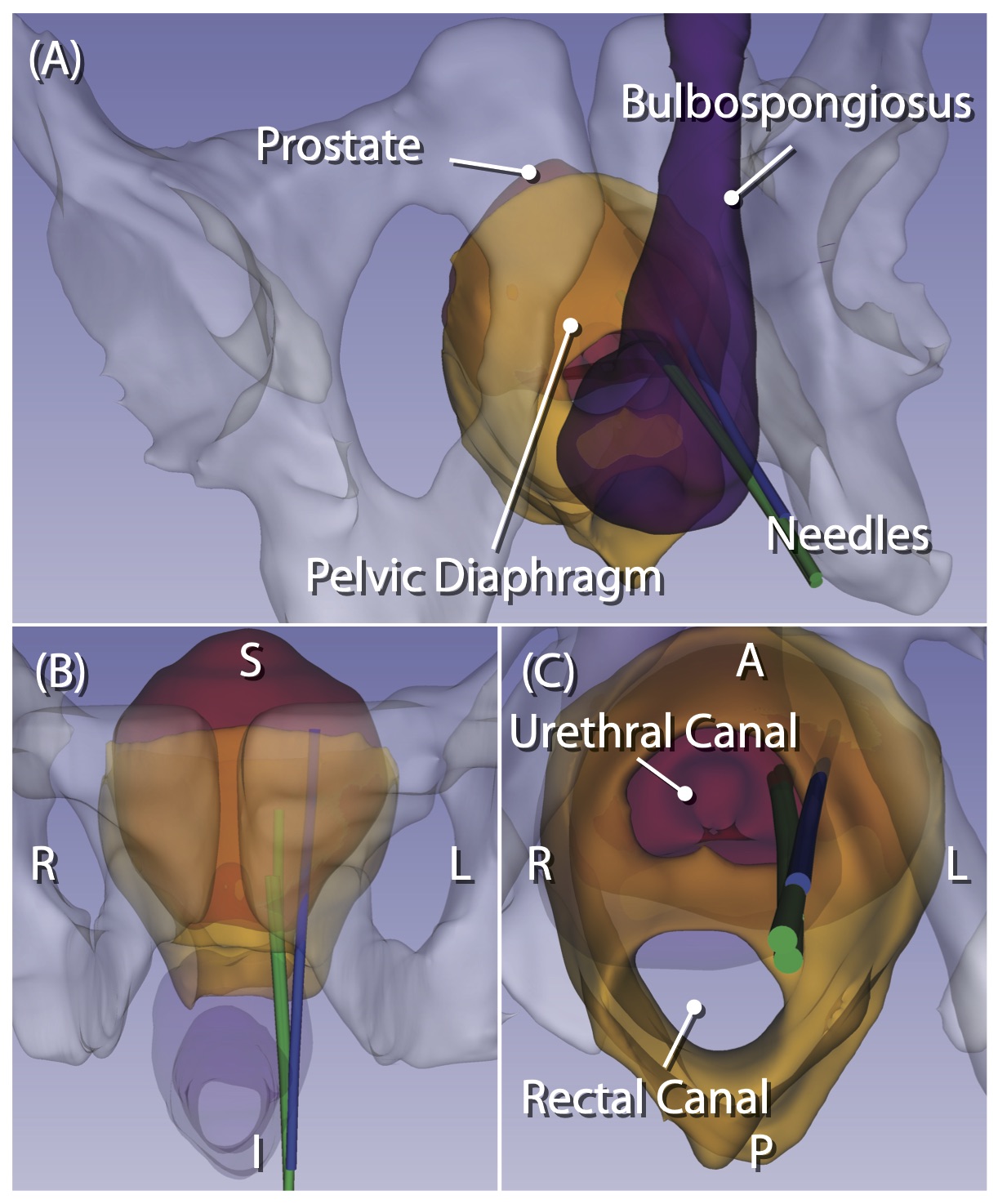
MRI-guided targeted prostate biopsy is becoming an integral part of prostate cancer diagnosis in recent years. Targeted biopsy is achieved by either performing the procedure in the MRI gantry (“in-bore MRI-guided biopsy”) or fusing preprocedural MR images onto transrectal ultrasound (TRUS) images during conventional TRUS-guided biopsy (“MRI fusion biopsy”). While MRI fusion biopsy has been more widely adopted thanks to its ease-of-use, in-bore MRI-guided biopsy is ideal for confirming the sampling location relative to the tumor. To assist with accurate tissue sampling in the MRI gantry, MRI-compatible needle-guide manipulators have been evaluated [1]. However, needle placement accuracy is often affected by the deviation of the needle. Recently, our study has shown that the extent of deviation depends on the anatomical structures along the needle path [2] (Fig 1). To avoid structures that are likely to cause significant needle deviation during transperineal needle insertion, we developed a 4-degree-of-freedom (DoF) needle-guide manipulator system named “Smart Template”. We evaluated the feasibility of needle placement using Smart Template under interactive real-time MRI guidance.Methods
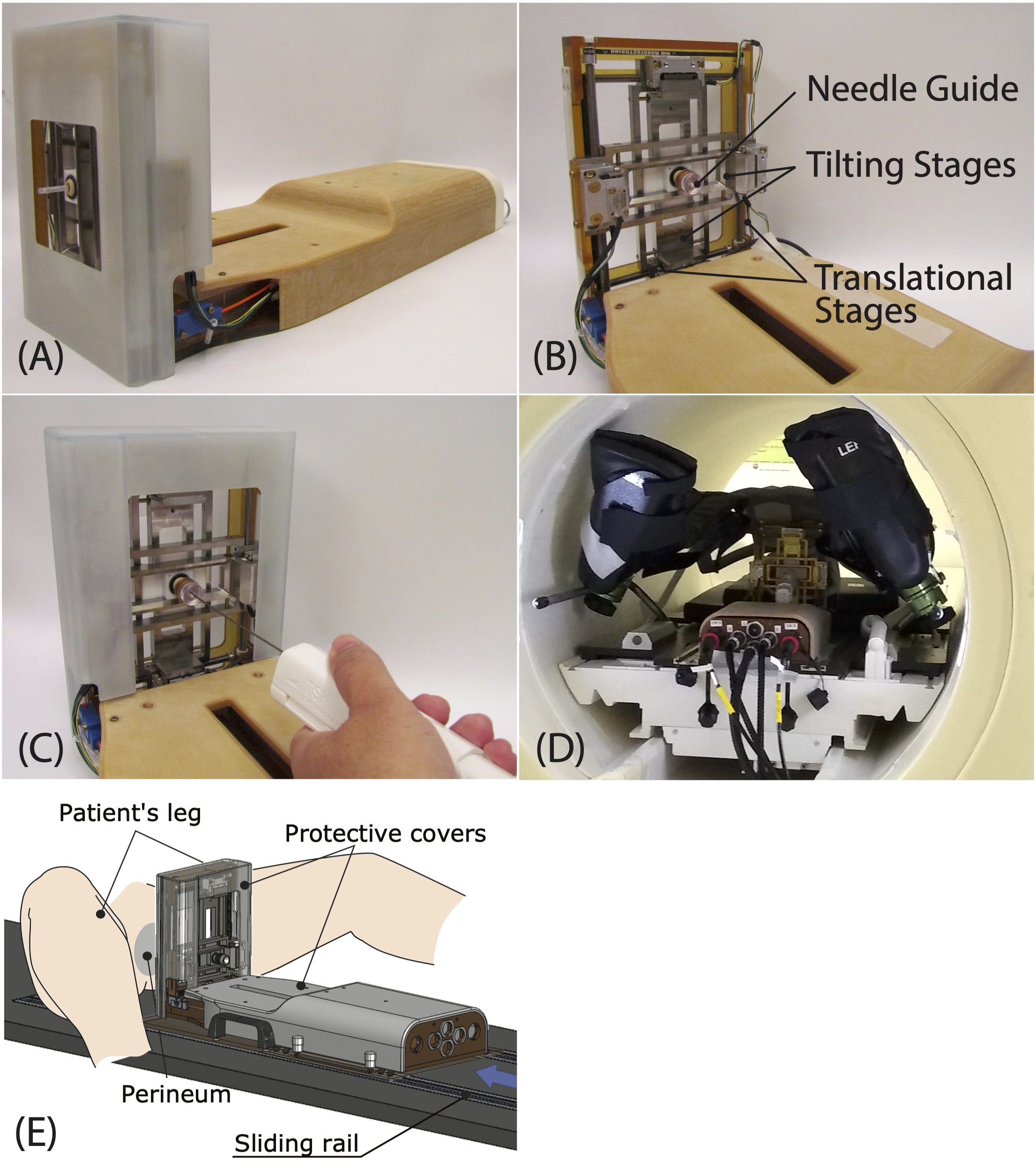
The system consists of the following components: (1) Manipulator. The Smart Template physically guides an 18-gauge core biopsy needle through the patient’s perineum with its needle guide aligned to a target lesion while a physician is inserting the needle. The needle guide is translated in the right-left and anterior-posterior directions by two ultrasonic motors (USR60-E3N, Shinsei Corp.) and tilted about these two axes by piezoelectric motors (Piezo LEGS LS1510D-B15, PiezoMotor Corp.) to adjust the position and orientation of the needle insertion path (Fig. 2). (2) Controller. The Smart Template is controlled by a low-power single-board computer that runs the Robot Operating System (ROS) on the Linux operating system. The ROS receives commands from Operator Interface software (e.g., target location and angulation) using OpenIGTLink [3] and controls individual motors via an integrated motion controller (DMC-4183, Galil Motion Control). (3) Operator Interface Software. The Operator Interface was built on 3D Slicer [4] with a SliceTracker plug-in [5]. It allows the operator to review pre- and intra-procedural MRI, define targets, and send commands to the Smart Template over the network. (4) Interactive Real-Time MRI Interface. The Operator Interface is connected to a 3T MRI scanner (Magnetom Verio, Siemens Healthcare, Erlangen, Germany) via prototype Scanner Remote Control (SRC). The scanner obtains the planned needle trajectory from the Operator Interface and acquires a real-time MR image from the scan plane aligned to the needle trajectory while the needle is being inserted.Experiments
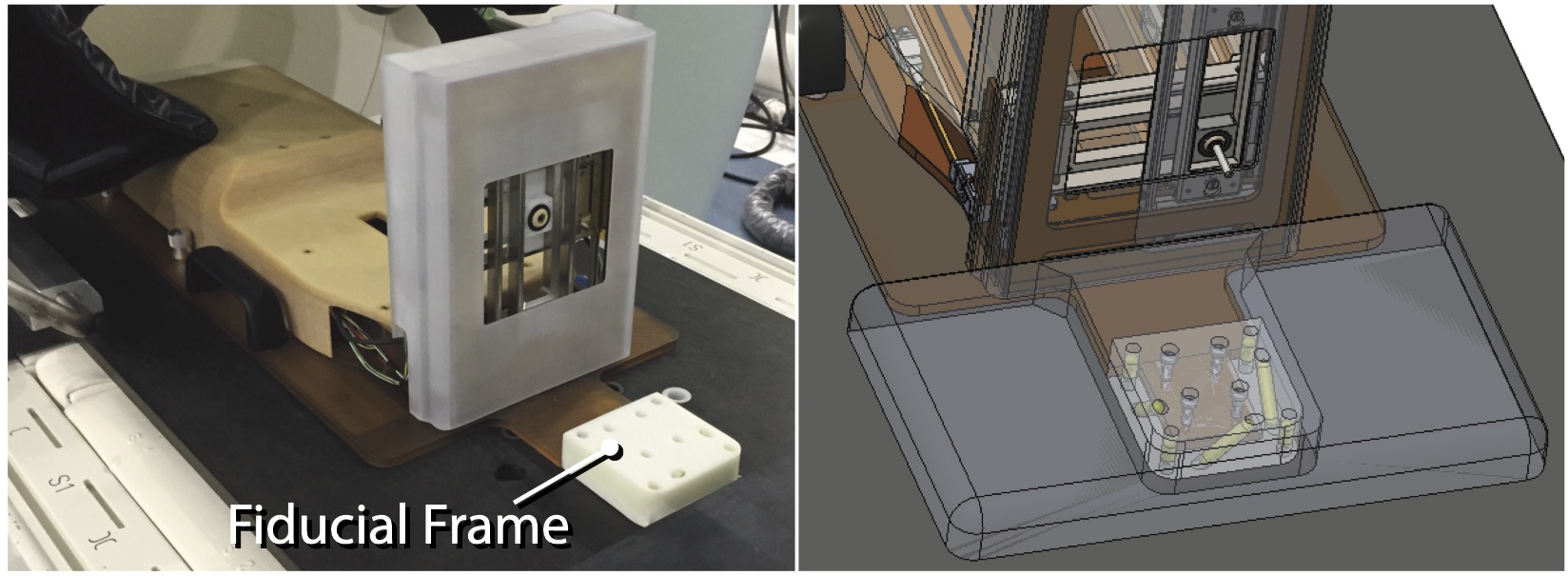
(1) Free-Space Needle Placement Accuracy Evaluation. The needle placement accuracy of the Smart Template was assessed in the free space. We targeted 22 randomly selected points at an insertion depth of 100 mm using straight (n=22) and angulated paths (n=22). For angulated paths, half of them (n=11) were angulated vertically within a range of ± 15°, and the remainder (n=11) were angulated horizontally within a range of ± 10°. The gold standard needle location was determined using a digital camera. (2) Preliminary Evaluation of Needle Placement Under Real-Time MRI Guidance. A gelatin phantom was placed at the isocenter of the scanner along with the Smart Template. The Smart Template was registered to the MRI coordinate system by imaging a fiducial frame attached to the Smart Template (Fig. 3) using a T2-weighted TSE sequence. Another multi-slice T2-weighted image of the phantom was obtained and transferred to the Operator Interface, where ten needle insertion paths were defined manually. The insertion paths and the imaging planes parallel to those paths were then sent to the controller and the SRC, respectively. After the needle guide was aligned with the planned path, an 18-gauge needle was then inserted, while acquiring real-time MRI images using a TrueFISP sequence (TR/TE=166.88/1.31ms, FA=30°, FOV=290mm2, slice thickness=10mm, matrix=128⨉128, PAT factor=2, TA=0.167s/frame). The final path of the needle was confirmed by acquiring a 3D image using a VIBE sequence. The distance between the target and the final needle path was measured on the image as a targeting accuracy.Results
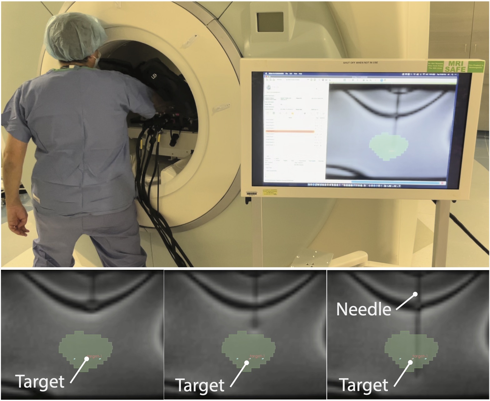
(1) Free-Space Needle Placement Accuracy Evaluation. The overall targeting accuracy was 1.3±0.7mm (mean ± SD), while the accuracies for straight and angulated insertions were 1.1±0.6mm, and 1.5±0.8mm, respectively. (2) Preliminary Needle Placement in Phantom Under Real-Time MRI Guidance. The needle was successfully inserted into the phantom using the Smart Template under real-time MRI guidance with an in-plane targeting accuracy of 2.9±0.6mm. The real-time imaging successfully captured the trajectory of the needle with a visualization latency of 0.66±0.23s on the in-room monitor (including acquisition, reconstruction, data transfer, and rendering), allowing the operator to monitor the advancement of the needle (Fig. 4).Discussion and Conclusion
Our preliminary evaluation demonstrates that needle insertion using the Smart Template under real-time MRI is feasible. The needle placement errors in the phantom study were biased along the horizontal axis, probably due to the fiducial-based registration, which had not been well tested and optimized yet for this specific application. The combination of angulated needle guidance and real-time image feedback will allow safe needle placement with minimum placement error.Acknowledgements
The study was funded in part by the National Institutes of Health (4R44CA224853, R01EB020667, R01CA235134, P41EB015898) and Siemens Healthineers. The SRC package was provided by Siemens as Work-in-Progress.References
[1] Schouten MG, et al. Evaluation of a Robotic Technique for Transrectal MRI-Guided Prostate Biopsies. Eur Radiol. 2012;22(2):476–83.
[2] Moreira P, et al. Evaluation of robot-assisted MRI-guided prostate biopsy: Needle path analysis during clinical trials. Phys Med Biol. 2018;63(20).
[3] Tokuda J, et al. OpenIGTLink: an open network protocol for image-guided therapy environment. Int J Med Robot Comput Assist Surg. 2009;5(4):423-434.
[4] Fedorov A, et al. 3D Slicer as an image computing platform for the Quantitative Imaging Network. Magn Reson Imaging. 2012;30(9):1323-1341.
[5] Herz C, et al. Open Source Platform for Transperineal In-Bore MRI-Guided Targeted Prostate Biopsy. IEEE Trans Biomed Eng. 2020;67(2):565-576.
Figures