4007
MRI Needle Tracking with Phase-only Cross-Correlation (POCC) in the Presence of Susceptibility Artifacts1Department of Radiology, Medical Physics, Medical Center – University of Freiburg, Faculty of Medicine, University of Freiburg, Freiburg, Germany
Synopsis
The phase-only cross correlation (POCC) algorithm can be used to accurately detect the orientation of a passive needle guide in needle interventions. A POCC sequence continuously visualizes the planned needle pathway during needle guide movement. The insertion of a needle into the needle guide, however, degrades the POCC detection because of susceptibility artifacts. In this work, susceptibility artifacts of a needle are measured and simulated, and a potential integration integrated into the POCC algorithm is evaluated.
Introduction
MR-guided interventions in closed bore MR systems benefit from interactive guidance during the procedure1. In percutaneous interventions with needles, often a cylindrical MR-visible marker with a central opening2 is used which delineates the desired needle pathway to facilitate the slice positioning. The needle guide can be further attached to an assistance system3 to increase targeting accuracy. Using a dedicated phase-only cross correlation (POCC) pulse sequence, the motion of the needle guide is then followed in real-time to assist during the targeting procedure4–8. The POCC sequence continuously re-aligns a targeting image parallel to the long axis of the needle guide, so that the needle pathway can be projected on the image. Therefore, the needle guide cross section is imaged in two tracking images, and the ring-like guide is detected automatically with a POCC template matching algorithm. In this algorithm, a synthetic reference image of an ideal needle guide cross section is precomputed. For a reliable detection of the needle guide the POCC algorithm requires that the image of the cross-section is free of artifacts. The insertion of a needle into the guide, however, causes image distortions because of susceptibility artifacts9–11. Thus, in current clinical applications, targeting is performed without the needle.To overcome this critical limitation, in this work, susceptibility artifacts of a needle are measured and simulated, so that they can later be integrated into the POCC algorithm to improve the template matching and the needle tracking.
Methods
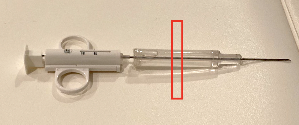
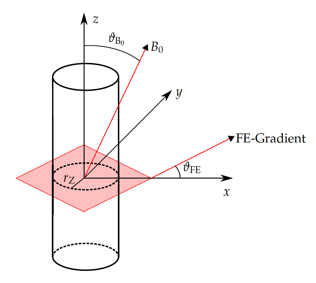
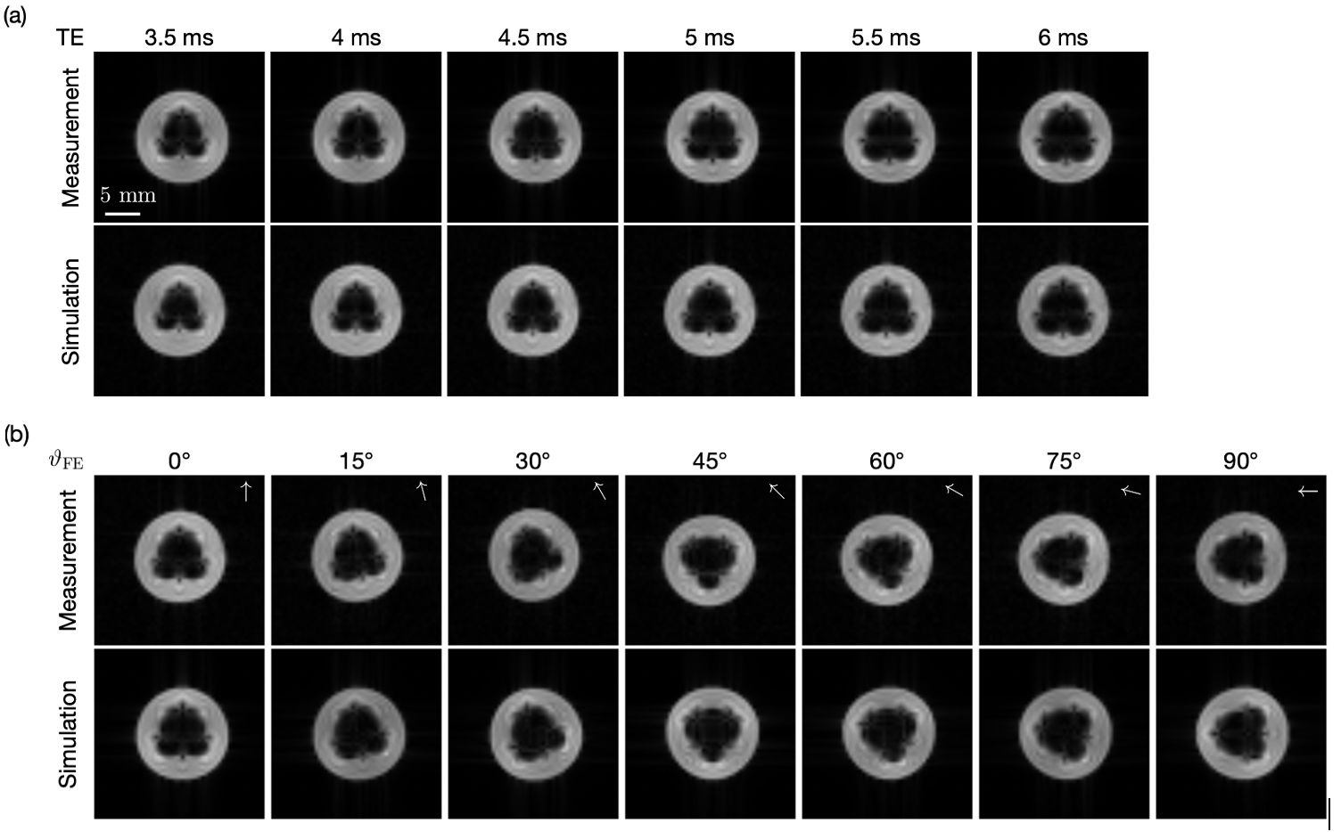
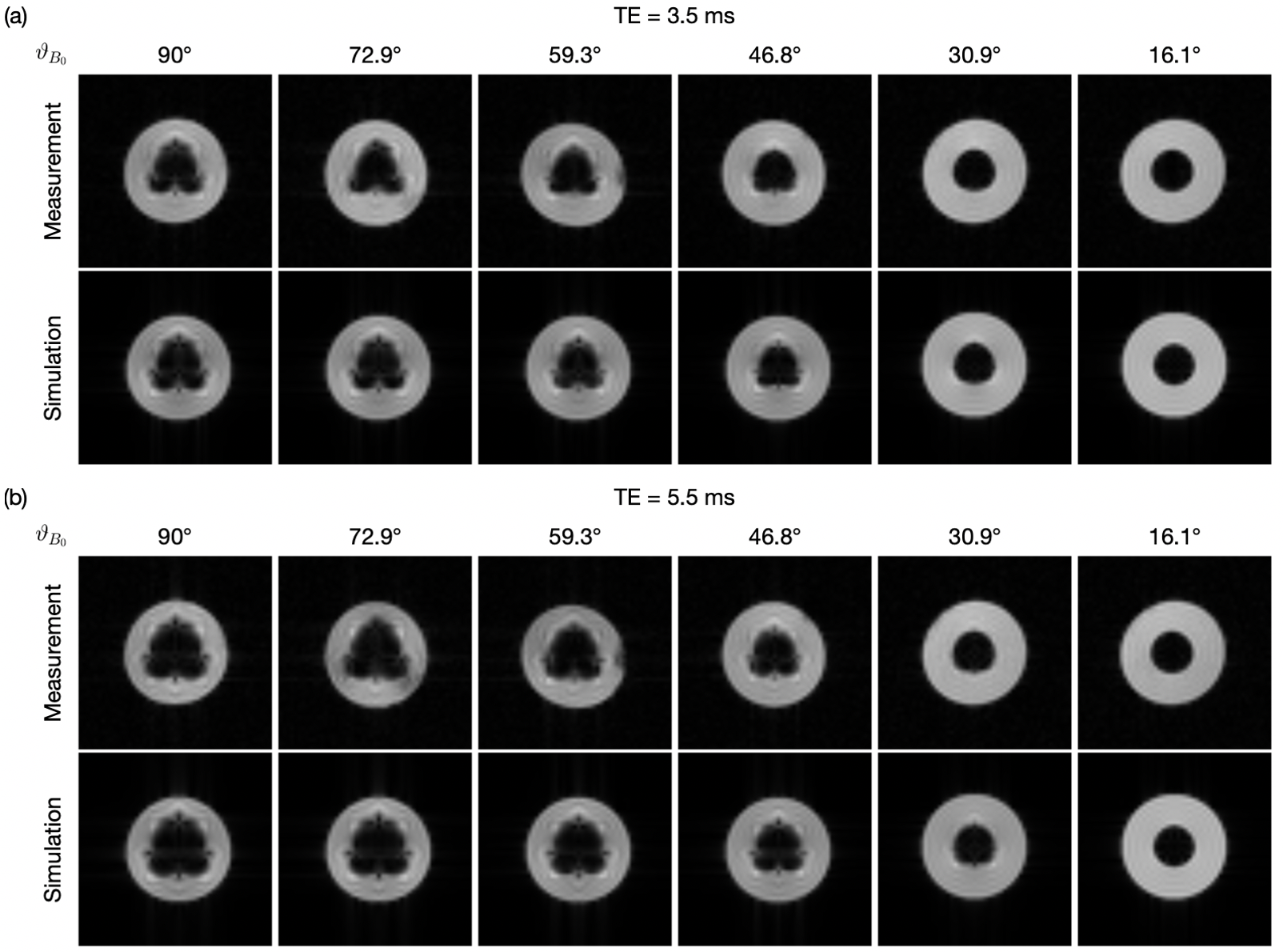
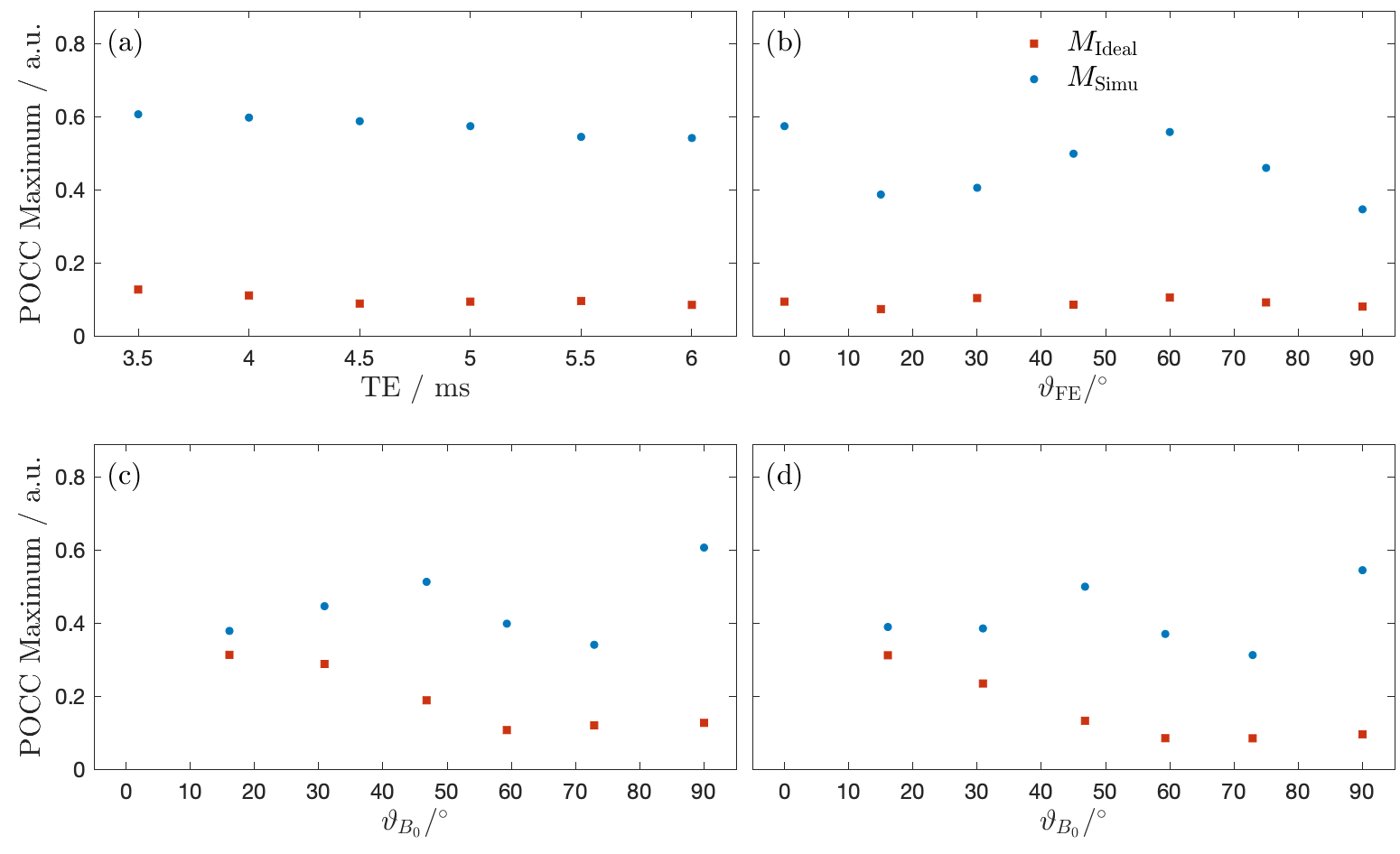
Needle artifact measurements were performed on a 1.5T clinical MRI system (Symphony, Siemens, Erlangen, Germany). For signal reception the system’s integrated spine array was used. A passive needle guide (inner diameter: 2.5mm, outer diameter: 6.5mm) filled with a contrast agent solution (Magnevist®/H2O: 1/200, Bayer Schering Pharma AG, Berlin, Germany) was placed approximately at the magnet isocenter. A commercially available biopsy canula (BIM 16/15, Innovative Tomography Products GmbH, Bochum, Germany; material: Nitinol, outer diameter: 16G = 1.6mm, length: 15mm) was inserted into the passive needle guide (Fig. 1). First, the needle guide with the needle was oriented perpendicular to the main magnetic field $$$B_0$$$ (i.e., $$$ϑ_{B_0} = 90°$$$ in Fig. 2). A slice was oriented perpendicular to the needle and images were acquired with a gradient echo sequence (TR=10 ms, flip angle=25°, field of view = 120mm2, matrix=256x256, bandwidth=434Hz/px, slice thickness = 10mm) for different echo times (TE = 3.5, 4.0,…, 6.0ms, Fig. 3a). Subsequently, the in-plane orientation of the readout direction ($$$ϑ_{FE}$$$ in Fig. 2) was varied in 15° steps for TE=5ms (Fig. 3b). Lastly, the orientation of the needle guide with respect to the $$$B_0$$$ ($$$ϑ_{B_0}$$$ in Fig. 2) was varied in steps of 15°, and images were again acquired perpendicular to the guide’s long axis for TE=3.5ms and TE=5.5ms (Fig. 4).Artifact simulations were performed with MATLAB (R2020b, MathWorks, Natick/MA). Magnetic field shifts produced by the needle were calculated analytically assuming an infinitely long Nitinol cylinder10 (susceptibility χ=300ppm) inside a passive needle guide filled with water (χ=-9ppm) and surrounded by air (χ=0.36ppm). The MR signal in the needle guide was simulated with the corresponding measurement parameters over an isochromat grid with size NIso = 5 assuming a steady-state condition12 (second row Fig. 2 - 4). The POCC $$POCC(x,y) = \frac{I(x,y)}{||I(x,y)||}\ast\frac{M(x,y)}{||M(x,y)||}$$ was calculated for each measured image $$$I(x,y)$$$ with an ideal, i.e. an undistorted image of the needle guide cross-section $$$M_\mathrm{Ideal}(x,y)$$$, and with the simulated images $$$M_\mathrm{Simu}(x,y)$$$ with susceptibility artifacts. To compare different POCC calculations, the value of the maximum of the POCC was determined for all parameter settings (Fig. 5).
Results
All susceptibility artifacts of the needle could be successfully reproduced in the simulations. The simulations show a good resemblance with measured images for all TEs, readout directions and orientations of the needle against $$$B_0$$$. As expected, the POCC maximum values calculated with the simulated images are higher when susceptibility artifacts are considered, as the simulated images better resemble with the measured cross sections and thus allow for a more robust detection of the needle guide. The average time needed for each simulation was 2.3 second.Discussion & Conclusion
The experiments demonstrate that simulations of needle artifacts could be successfully integrated into the POCC template matching algorithm. The time needed for the simulations suggest that with some further optimization the artifact images could be calculated in the real-time image reconstruction framework of the MRI which would allow detecting the needle guide even with an inserted needle. Integration of a radial acquisition scheme for needle detection could further reduce the acquisition time needed13. Monitoring of the needle insertion and tracking of the needle tip in the targeting images could be performed with dedicated sequences13,14 or with spin echo based sequences that are less prone to needle artifacts.Acknowledgements
This work was supported in parts by a grant from the German Federal Ministry for Economic Affairs and Energy (BMWi) under the grant program “Zentrales Innovationsprogramm Mittelstand (ZIM),” grant number ZF4535603BA9, as part of the IraSME funding “E‐GantryMate.” The authors thank Michael Vogele (Interventional Systems, Kitzbuehel, Austria) for providing the passive needle guide and Werner Henke (Innovative Tomography Products GmbH, Bochum, Germany) for providing the biopsy canula.References
1. Busse, H., Kahn, T. & Moche, M. Techniques for Interventional MRI Guidance in Closed-Bore Systems. Top. Magn. Reson. Imaging 27, 9–18 (2018).
2. Beyersdorff, D. et al. MR Imaging–guided Prostate Biopsy with a Closed MR Unit at 1.5 T: Initial Results. Radiology 234, 576–581 (2005).
3. Reichert, A., Bock, M., Vogele, M. & Joachim Krafft, A. GantryMate: A Modular MR-Compatible Assistance System for MR-Guided Needle Interventions. Tomography 5, 266–273 (2019).
4. de Oliveira, A., Rauschenberg, J., Beyersdorff, D., Semmler, W. & Bock, M. Automatic passive tracking of an endorectal prostate biopsy device using phase-only cross-correlation. Magn. Reson. Med. 59, 1043–1050 (2008).
5. Krafft, A. J. et al. Passive marker tracking via phase-only cross correlation (POCC) for MR-guided needle interventions: Initial in vivo experience. Phys. Med. 29, 607–614 (2013).
6. Zamecnik, P. et al. Automated Real-time Needle-Guide Tracking for Fast 3-T MR-guided Transrectal Prostate Biopsy: A Feasibility Study. Radiology 273, 879–886 (2014).
7. Reichert, A. et al. Simultaneous slice excitation for accelerated passive marker tracking via phase-only cross correlation (POCC) in MR-guided needle interventions. Magn. Reson. Mater. Phys. Biol. Med. 31, 781–788 (2018).
8. Reichert, A., Reiss, S., Krafft, A. J. & Bock, M. Passive needle guide tracking with radial acquisition and phase-only cross-correlation. Magn. Reson. Med. 85, 1039–1046 (2021).
9. Lüdeke, K. M., Röschmann, P. & Tischler, R. Susceptibility artefacts in NMR imaging. Magn. Reson. Imaging 3, 329–343 (1985).
10. Ladd, M. E. et al. Biopsy needle susceptibility artifacts. Magn. Reson. Med. 36, 646–651 (1996).
11. Liu, H., Martin, A. J. & Truwit, C. L. Interventional MRI at high-field (1.5 T): Needle artifacts. J. Magn. Reson. Imaging 8, 214–219 (1998).
12. Zijlstra, F., Bouwman, J. G., Braškutė, I., Viergever, M. A. & Seevinck, P. R. Fast Fourier-based simulation of off-resonance artifacts in steady-state gradient echo MRI applied to metal object localization. Magn. Reson. Med. 78, 2035–2041 (2017).
13. Zijlstra, F., Viergever, M. A. & Seevinck, P. R. SMART tracking: Simultaneous anatomical imaging and real-time passive device tracking for MR-guided interventions. Phys. Med. 64, 252–260 (2019).
14. Weber, H., Hargreaves, B. A. & Daniel, B. L. Artifact-reduced imaging of biopsy needles with 2D multispectral imaging. Magn. Reson. Med. 80, 655–661 (2018).
Figures