3962
Improved B0 mapping with universal parallel transmit pulses at 7 tesla1Institue of Neuroradiology, University Hospital Erlangen, Erlangen, Germany, 2SIEMENS Healthineers, Erlangen, Germany, 3Imaging Centre of Excellence, University of Glasgow, Glasgow, Scotland, 4Institue of Radiology, University Hospital Erlangen, Erlangen, Germany, 5Friedrich Alexander University Erlangen Nürnberg, Erlangen, Germany
Synopsis
B0 mapping was performed with a circularly polarized pulse and with a non-selective universal parallel transmit (pTx) pulse. The pTx pulse showed improved homogeneity, which resulted in different B0 values, mainly present at tissue interfaces. Based on the two resulting B0 maps, patient specific B0 shimming was performed. Further, based on the two shimmed B0 maps, individually optimized pTx excitation and inversion pulses were designed for use in a 3D MPRAGE sequence. The pTx inversion pulse based on the B0 map, which itself used universal pTx pulse, achieved a reduction of B0 related artifacts in the frontal sinus region.
The inhomogeneous transmit (B1+) fiels in MRI at 7 tesla cause regions of low signal intensity. In addition, B0 inhomogeneities get more pronounced at higher field strengths, which often result in image artifacts. Dynamic parallel transmit (pTx) pulses can be used to produce uniform flip angle (FA) distributions throughout the head despite of the present field inhomogeneities [1]. Since the design of pTx pulses makes use of subject specific B1+ and B0 maps, the performance of the pTx pulses depends on the accuracy of these fieldmaps. B0 maps are typically acquired with multi-echo gradient echo sequences, yet these images themselves may also suffer from the mentioned field inhomogeneities [2]. The aim of this work was to implement pTx excitation pulses into a B0 mapping sequence. The sequence was equipped with either a circularly polarized (CP) excitation pulse or a pTx universal pulse (UP) [3]. The resulting maps were used for patient specific B0 shimming, which themselves were used for designing pTx excitation and inversion pulses for use in a 3D MPRAGE sequence.
Methods
Four B0 maps of a single volunteer were acquired using a 3D sagittally oriented gradient echo sequence (TE1 = 2.39s, TE2 = 4.59s, TE3 = 7.09s; 4mm3; TA = 12s). The sequence made use of either a CP pulse or a pTx UP described below, as well as either default shim currents or a patient specific brain shimming with a vendor provided method. They are denoted respectively, whereby the subscript ‘CP’ or ‘UP’ denotes used excitation pulse, and an added subscript ‘shim’ indicates patient specific shimming: ‘B0CP/B0UP/B0CP, shim/B0UP, shim’.
The non-selective pTx UP used in the B0 mapping sequence was designed using head datasets (B1+, B0 maps using CP pulses) of eight previously examined healthy volunteers. It was based on an extended SPINS k-space trajectory [4, 5] (target FA: 5°, duration: 1ms). The trajectory parameters and energy regularization weights were defined as ‘Combined Optimization Values’ (COV) for simultaneous optimization (see [5]). Universal pulse shapes were generated based on these COV, using the Variable Exchange algorithm [6].
For evaluation, in total four Fast Online Customized (FOCUS) pTx pulses were designed for excitation and inversion. Their design made use of the different brain shimmed B0 maps, both B0CP, shim and B0UP, shim, as well as B1+ maps of each transmit channel, which were acquired with a magnetization-prepared saturation-recovery TurboFLASH sequence (TA = 35s) [7] using CP pulses. The FOCUS excitation pulses were based on the UP used for B0 mapping, yet with further optimized RF shapes. The inversion pulses were generated similarly, yet with a kT point trajectory [8] (COV consisted of kT point locations, their respective subpulse durations and an energy regularization weight), a pulse duration of 4.8ms and an interior-point based pulse shape optimization algorithm [9].
Results and Discussion
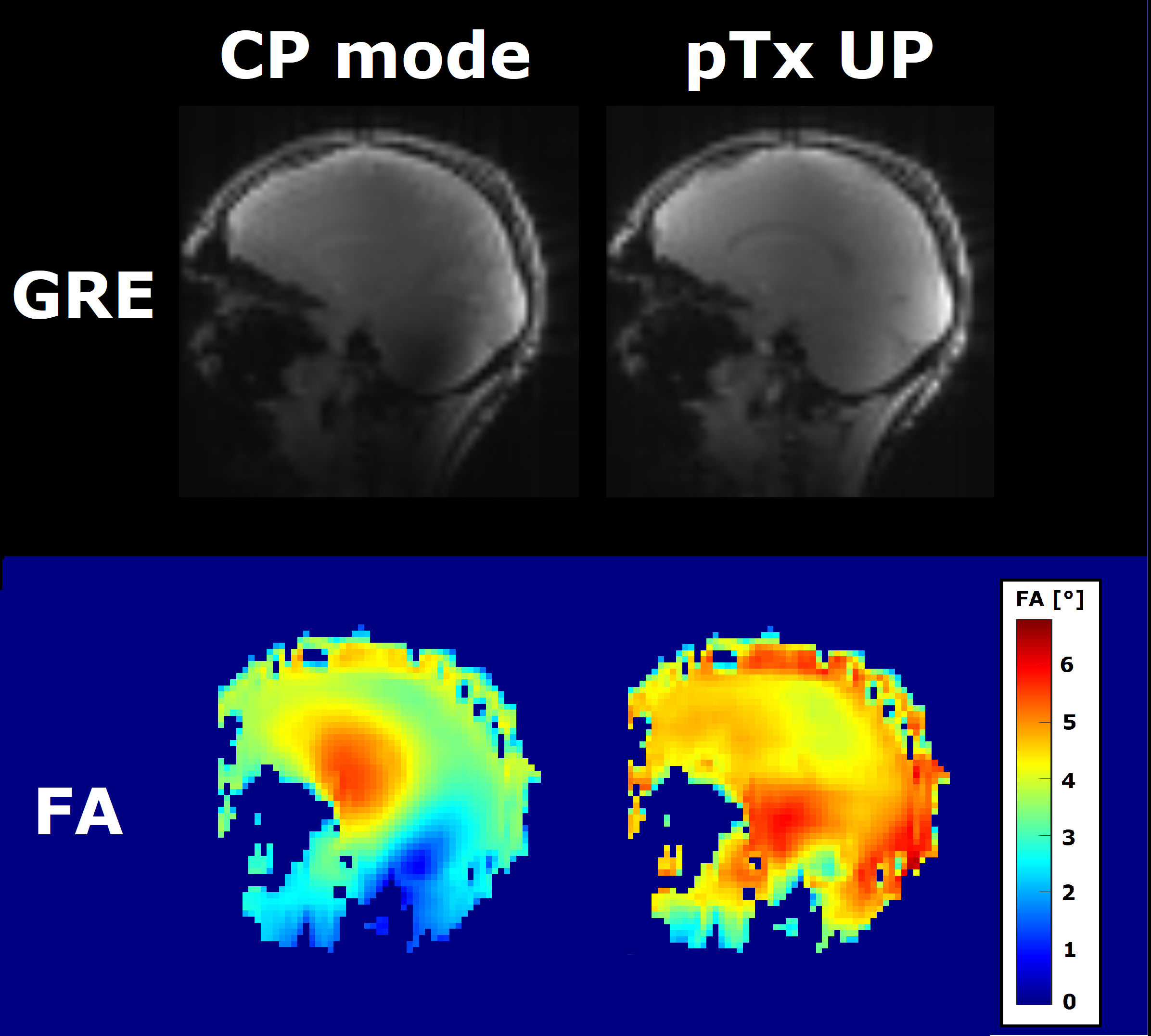
Figure 1 shows the first gradient echo of the B0 mapping sequences with either CP mode or a UP and their respective simulated FA maps. While the CP pulse shows signal variations throughout the brain and low signal especially in the cerebellum region (NRMSE = 26.9%), the UP shows improved signal homogeneity (NRMSE = 14.2%).
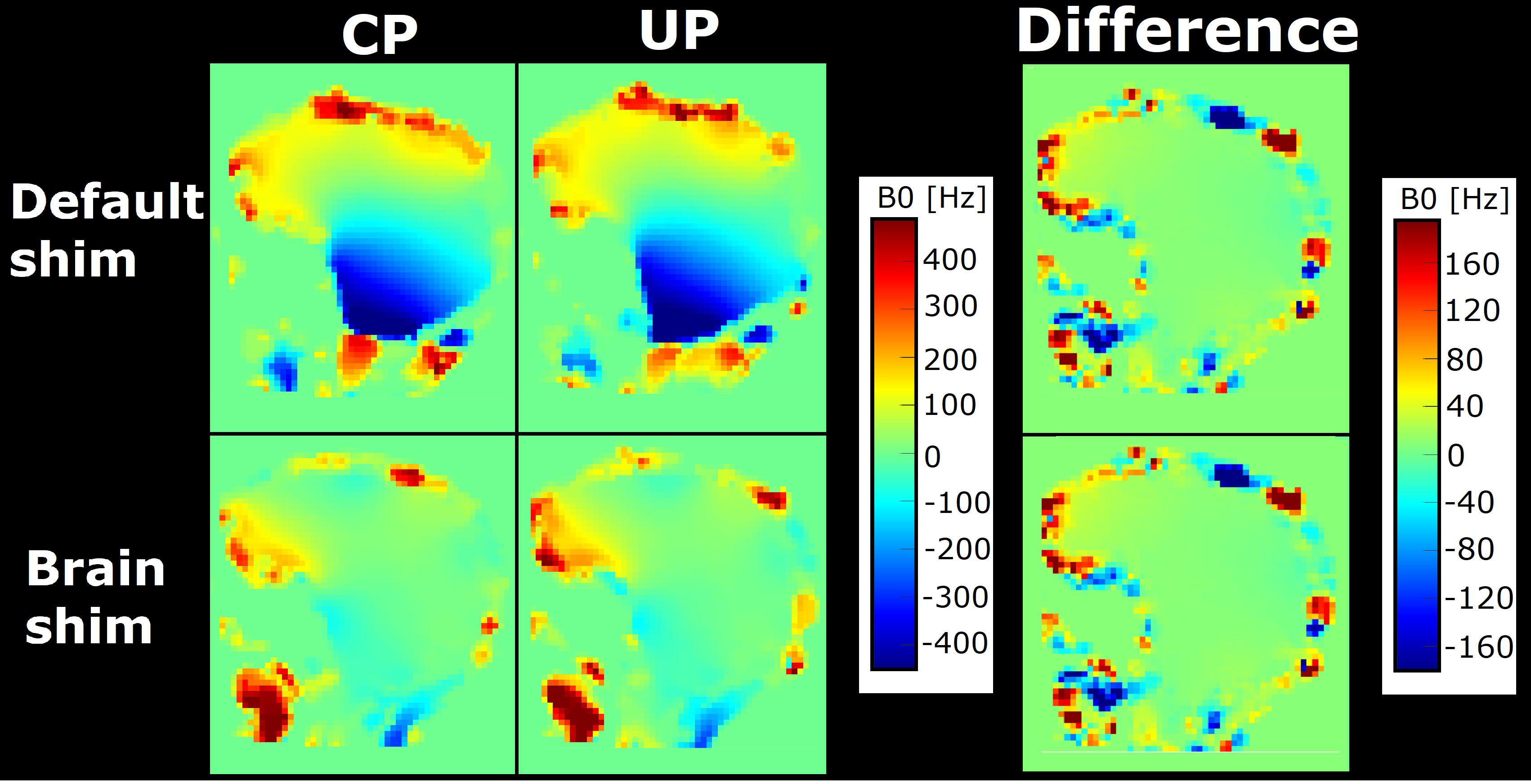
Figure 2 shows an example slice of the maps B0CP/B0UP/B0CP, shim/B0UP, shim in off-resonance frequency units [Hz], as well as the differences between B0CP, shim and B0UP, shim with different pulses. Note that for patient specific brain shimming, the difference between B0CP and B0UP lead to different shim currents. The effect of the brain shim appears similar for both pulses. The highest offsets in the shimmed maps, as well as highest differences between them mainly occur at tissue interfaces. Motion correction was not performed.
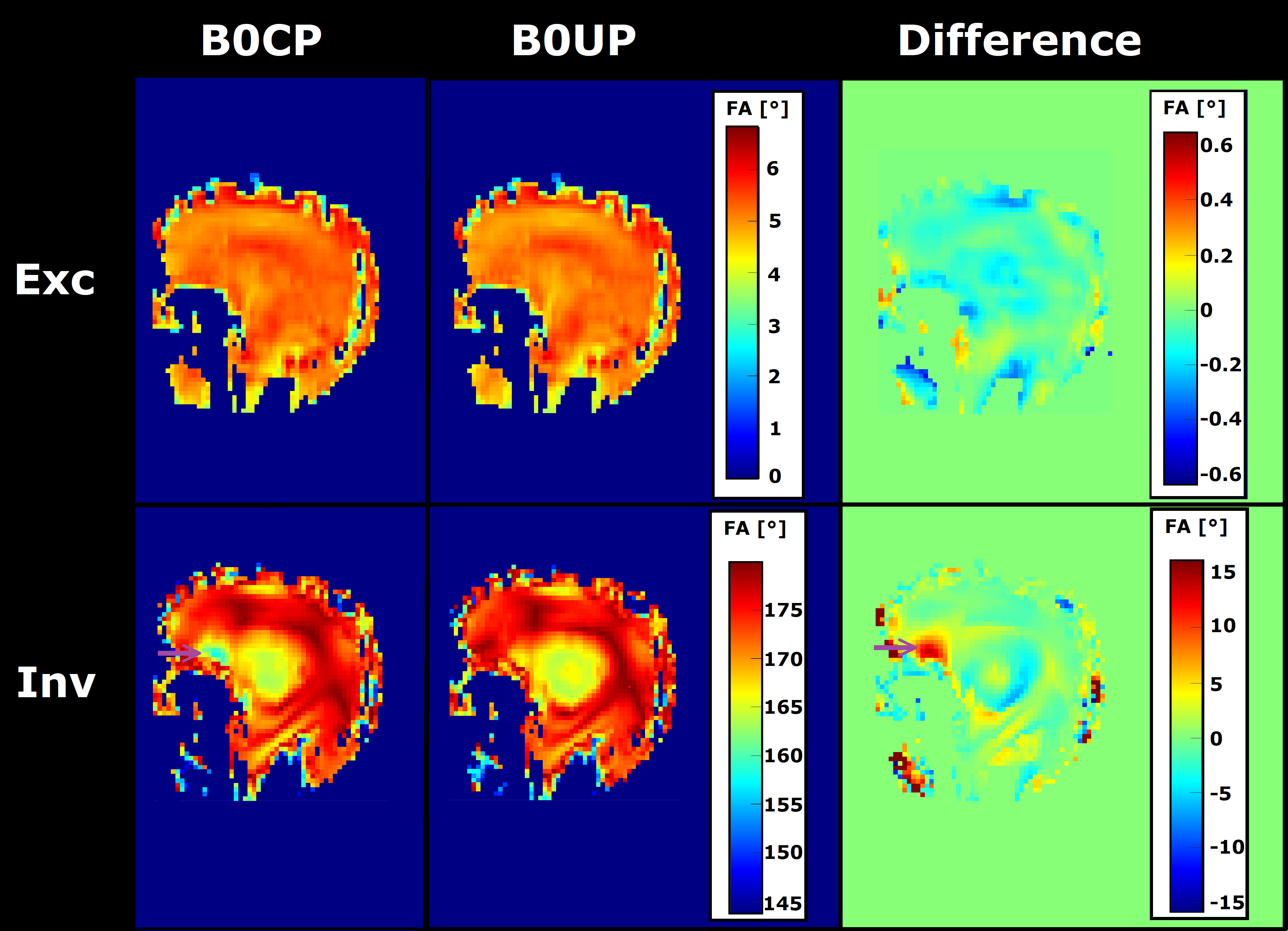
Figure 3 shows FA simulations of FOCUS pulses for excitation and inversion pulses optimized with the shimmed B0 maps. Differences between the excitation pulses caused by the differences in the B0 maps are in a range of -0.5° to 0.5°. In the case of the inversion pulses, the one based on B0CP, shim showed an up to 15° lower FA in the sinus region.
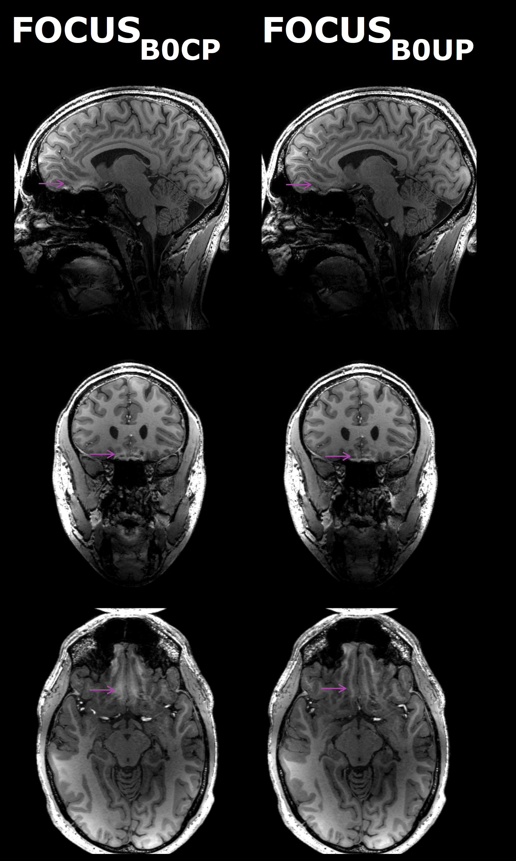
Figure 4 shows resulting MPRAGE images, when using FOCUS pulses based on either B0CP, shim or B0UP, shim for excitation and inversion. The FOCUS inversion pulse based on B0CP, shim showed weaker performance in the frontal sinus region, and the corresponding MPRAGE image shows a B0 related artifact in this region. This artifact is reduced, yet still present when using a FOCUS inversion pulse based on B0UP, shim. Effects caused by the different excitation pulses could not be observed.
Notably, the improved signal strength in the cerebellum, achieved by the UP (Figure 1) did not result in significant differences in the performance of FOCUS pTx pulses in this particular region.
Conclusion
Acquiring B0 inhomogeneities with a preoptimized pTx UP has minor impact on the behavior of pTx excitation pulses, yet it may be crucial for designing pTx inversion pulses. There B0 artifacts can be reduced. Further investigations involving gold standard B0 mapping sequences, as well as measuring B1+ map inaccuracies and reducing them with pTx pulses, are still required. Additionally, the potential of reciprocally improving B0/B1+ mapping and pTx pulses remains to be explored.
Acknowledgements
No acknowledgement found.References
1. Ladd, M.E., et al., Pros and cons of ultra-high-field MRI/MRS for human application. Prog Nucl Magn Reson Spectrosc, 2018. 109: p. 1-50.
2. Nehrke, K. and P. Bornert, DREAM--a novel approach for robust, ultrafast, multislice B(1) mapping. Magn Reson Med, 2012. 68(5): p. 1517-26.
3. Gras, V., et al., Universal pulses: A new concept for calibration-free parallel transmission. Magn Reson Med, 2017. 77(2): p. 635-643.
4. Malik, S.J., et al., Tailored excitation in 3D with spiral nonselective (SPINS) RF pulses. Magn Reson Med, 2012. 67(5): p. 1303-15.
5. Herrler, J., et al., Fast Online-Customized (FOCUS) Parallel Transmission Pulses: A Combination of Universal Pulses and Individual Optimization. Magnetic Resonance in Medicine, 2020.
6. Setsompop, K., et al., Magnitude least squares optimization for parallel radio frequency excitation design demonstrated at 7 Tesla with eight channels. Magn Reson Med, 2008. 59(4): p. 908-15. 7. Hans-Peter Fautz, M.V., P. Gross, A. Kerr, Y. Zhu. B1 mapping of coil arrays for parallel transmission. in International Society for Magnetic Resonance in Medicine. 2008. Toronto.
8. Cloos, M.A., et al., kT -points: short three-dimensional tailored RF pulses for flip-angle homogenization over an extended volume. Magn Reson Med, 2012. 67(1): p. 72-80.
9. Majewski, K. and D. Ritter, First and second order derivatives for optimizing parallel RF excitation waveforms. J Magn Reson, 2015. 258: p. 65-80.
Figures