3960
Exploring RF pulse design with deep reinforcement learning1Center for Magnetic Resonance Research, Radiology, Medical School, University of Minnesota, Minneapolis, MN, United States
Synopsis
In this study, we expand the application of a deep reinforcement learning (DRL) pulse design framework to designing four basic types of RF pulses and more complicated multi-band RF pulses. Our results showed that the DRL framework can be used to effectively design all types of RF pulses, improving slice profiles with reduced ripple levels in comparison to the conventional SLR algorithm.
Purpose
Recent studies have demonstrated the value of deep learning in RF pulse design1-4. Particularly, deep reinforcement learning (DRL)5 was shown able to predict an RF pulse with specified design criteria3. Here, we expand its application to five pulse design scenarios: small-tip-angle excitation, 90-degree excitation, refocusing, inversion and multi-band 90-degree excitation.Methods
Our DRL pulse design framework entailed an artificial agent learning from interactions with its environment (Fig. 1). The agent was a deep neural network and the environment involved a Bloch simulator.The training in each episode (i.e. iteration) was as follows: 1) the agent made observation by taking the target slice profile as input and took action by predicting RF pulse; 2) the predicted RF pulse was fed (along with a constant gradient) to the Bloch simulator to produce the corresponding slice profile; 3) the produced slice profile was used to evaluate a reward with which to update the neural network. The neural network was trained by minimizing the loss (instead of maximizing the reward) using Adam algorithm6. The loss was calculated by
$$loss=\lambda_{1}\cdot{MSE_{-}M_{xy}}+\left(1-\lambda_{1}\right)\cdot{MSE_{-}M_{z}}+\lambda_{2}\cdot{R_{-}M_{xy}}+\lambda_{3}\cdot{R_{-}M_{z}}$$
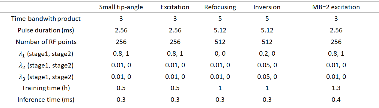
where MSE_Mxy and MSE_Mz are mean squared error (MSE) for transverse and longitudinal components, respectively, used to quantify the deviation of the produced slice profile from the target; R_Mxy and R_Mz are the corresponding ripple levels, defined as sum of the min-max magnitude difference in passband and stopband; λ1, λ2 and λ3 are three hyperparameters tunable to adjust the weightings of individual terms.
For ease of training, the target slice profile was relaxed to a trapezoid shape, with the transition band calculated by the SLR algorithm for 0.01 passband and stopband ripple levels7.
For each design scenario, an independent neural network was trained using a custom two-stage optimization. λ1, λ2 and λ3 in the loss definition were adapted (Fig. 2) from stage to stage such that the first stage was devised to reduce both MSE and ripples while the second stage to purely minimize MSE. Further, λ1 was set to a value close to 1 for excitation pulse designs (to consider mostly Mxy) and a value close to 0 for refocusing and inversion pulse designs (to consider mostly Mz).
Although the neural networks in all design scenarios shared the same architecture of 6 fully-connected layers (including 4 hidden layers each with ReLU activation and 256 neurons), they differed in the output layer. The output layer was designed to output the entire RF waveform for inversion pulse design, whereas it was devised to predict only the first half of the RF waveform (with the second half mirroring the first half) for all the other design scenarios requiring a linear-phase slice profile.
For the small-tip-angle scenario, the single neural network was trained by randomly sampling a pool of target slice profiles prescribed for flip angles from 5 to 80 degrees (in steps of 5 degree) to promote its generalizability. In all scenarios, real-valued RF pulses were predicted, the slice thickness was set to 3 mm, and a total of 400 episodes carried out (300 for stage 1 and 100 for stage 2).
Our DRL framework was implemented using the Flux package in Julia8 and all networks trained on a Linux workstation using CPU without parallel computation. For comparison, pulses were also designed with the SLR algorithm7.
Results
Our DRL method substantially reduced the slice profile MSE for all pulse design scenarios (Fig. 3) when comparing the resultant slice profile against the target trapezoidal slice profile, and MSE was decreased the most for multiband excitation pulse design (by as high as 86%). When comparing the resultant slice profile against the ideal rectangular slice profile, our DRL method outperformed SLR for flip angles up to 90 degrees, with MSE decreased most for small tip angle excitation (by 15%), though slice profile was moderately degraded (by <10%) for refocusing, and slightly degraded (<1%) for inversion.The improvement in slice profile for small tip angle pulse design was further confirmed by inspecting the resultant slice profiles of representative flip angles (Fig. 4). For a wide range of flip angles, our DRL method gave rise to a slice profile closer to both target and ideal slice profiles, with more flattened passband observed for relatively small tip angles and with less stopband ripples for relatively large tip angles.
Likewise, our DRL method improved slice profiles for single band and multiband excitation pulses with noticeable suppression of stopband ripples, while leading to visually comparable slice profiles for refocusing and inversion (Fig. 5).
The predicted RF pulses, however, are not as smooth as those from SLR and have increased peak B1.
Discussion and Conclusion
We have demonstrated a deep reinforcement learning framework to design various RF pulses. Our results showed that our DRL framework can effectively predict excitation, refocusing, inversion and multiband excitation pulses for a given target slice profile, with improved performance in ripple suppression as compared to the conventional SLR pulse design algorithm.Part of our future work is to investigate how best to reduce peak B1 and to examine the utility of other neural network architectures (e.g., RNN9 and ResNet10).
Acknowledgements
This work was supported by NIH grants U01 EB025144, and P41 EB015894.References
1. inding MS, Skyum B, Sangill R, et al. Ultrafast (milliseconds), multidimensional RF pulse design with deep learning. Magn Reson Med 2019;82:586-599
2. Shin D, Ji S, Lee D, et al. Deep Reinforcement Learning Designed Shinnar-Le Roux RF Pulse Using Root-Flipping: DeepRFSLR. IEEE Trans Med Imaging 2020;39:4391-4400
3. Shin D, Lee J. DeepRF: Designing an RF pulse using a self-learning machine. Proc Intl Soc Mag Reson Med 2020:0611
4. Zhang Y, Jiang K, Jiang W, et al. Multi-task convolutional neural network-based design of radio frequency pulse and the accompanying gradients for magnetic resonance imaging. NMR Biomed 2020:e4443
5. Sutton RS, Barto AG. Reinforcement Learning: An Introduction. 2020
6. Kingma DP, Ba J. Adam: A method for stochastic optimization. arXiv preprint arXiv:14126980 2014
7. Pauly J, Le Roux P, Nishimura D, et al. Parameter relations for the Shinnar-Le Roux selective excitation pulse design algorithm [NMR imaging]. IEEE Trans Med Imaging 1991;10:53-65
8. Innes M. Flux: Elegant machine learning with Julia. Journal of Open Source Software 2018;3:602
9. David ER, James LM. Learning Internal Representations by Error Propagation. Parallel Distributed Processing: Explorations in the Microstructure of Cognition: Foundations: MIT Press; 1987:318-362
10. He KM, Zhang XY, Ren SQ, et al. Deep Residual Learning for Image Recognition. 2016 Ieee Conference on Computer Vision and Pattern Recognition (Cvpr) 2016:770-778
Figures