3953
3D k-Space Domain Parallel Transmit Pulse Design1Department of Radiology, Stanford University, Stanford, CA, United States, 2Department of Biomedical Engineering, Vanderbilt University, Nashville, TN, United States, 3A. A. Martinos Center for Biomedical Imaging, Massachusetts General Hospital, Harvard Medical School, Charlestown, MA, United States, 4Division MR Physics, Center for Medical Physics and Biomedical Engineering, Medical University Vienna, Vienna, Austria, 5Department of Radiology and Radiological Sciences, Vanderbilt University, Nashville, TN, United States
Synopsis
Current parallel transmit pulse design is based on a spatial domain formulation that has prohibitive memory and computational requirements when the number of coils or the number of dimensions is large. We previously introduced a k-space domain method that produces a sparse matrix relating any target excitation pattern in k-space to the pulses that produce it, which can be finely parallelized, has much smaller memory footprint, and can compensate off-resonance. Here we validate the algorithm for 3D inner-volume excitation using a simulated 24-channel transmit array and a SPINS trajectory, with comparisons to conventional iterative spatial domain designs.
Introduction
Parallel-transmission (pTx) enables the excitation of multidimensional selective patterns with short RF durations1,2. The spatial domain formulation is currently the most widely used approach for pTx pulse design3, but for large problem sizes (as in high-resolution 2D pulse design, many-coil parallel excitation, 3D and spectral-spatial pulse design), matrix inverse and iterative solutions have large memory and/or computational requirements. We have previously introduced a k-space-based approach to pTx pulse design that has low memory and computational requirements and is highly parallelizable, and validated it with 2D spiral designs4,5. It solves for a sparse matrix W that relates the discrete Fourier transform of a target pattern d to a vector of RF pulses, as:$$\mathbf{b} = \mathbf{W} \mathcal{F}(\mathbf{d}),$$
where the designed pulses are stacked end-on-end in the vector b. The problem of solving W can be broken down into subproblems of solving its columns, each independent and small, and therefore can be accelerated by parallel computing. This advantageous property is based on the fact that for each point in the k-space target pattern, only a small number of excitation trajectory points near it can contribute significantly to it or its neighbors, and therefore need to be considered in the independent subproblem. Through derivation shown in Ref 5, the solution of each column of W is
$$\mathbf{w}=\left( \mathbf{S}^{H} \mathbf{S} + \lambda \mathbf{I} \right) ^{-1} \mathbf{s}^{H},$$
where each column of S is the Fourier transform of one channel’s B1+ map, shifted to be centered at an excitation k-space location. The SHS matrix is efficiently constructed via interpolation of the Fourier transforms of products of pairs of B1+ maps6, eliminating the construction and multiplication of the long S matrix. We have also incorporated off-resonance compensation through a time-segmented model in the proposed k-space domain algorithm, which is common in spatial-domain parallel pulse designs3, but has not been previously implemented in a k-space domain design.
Methods
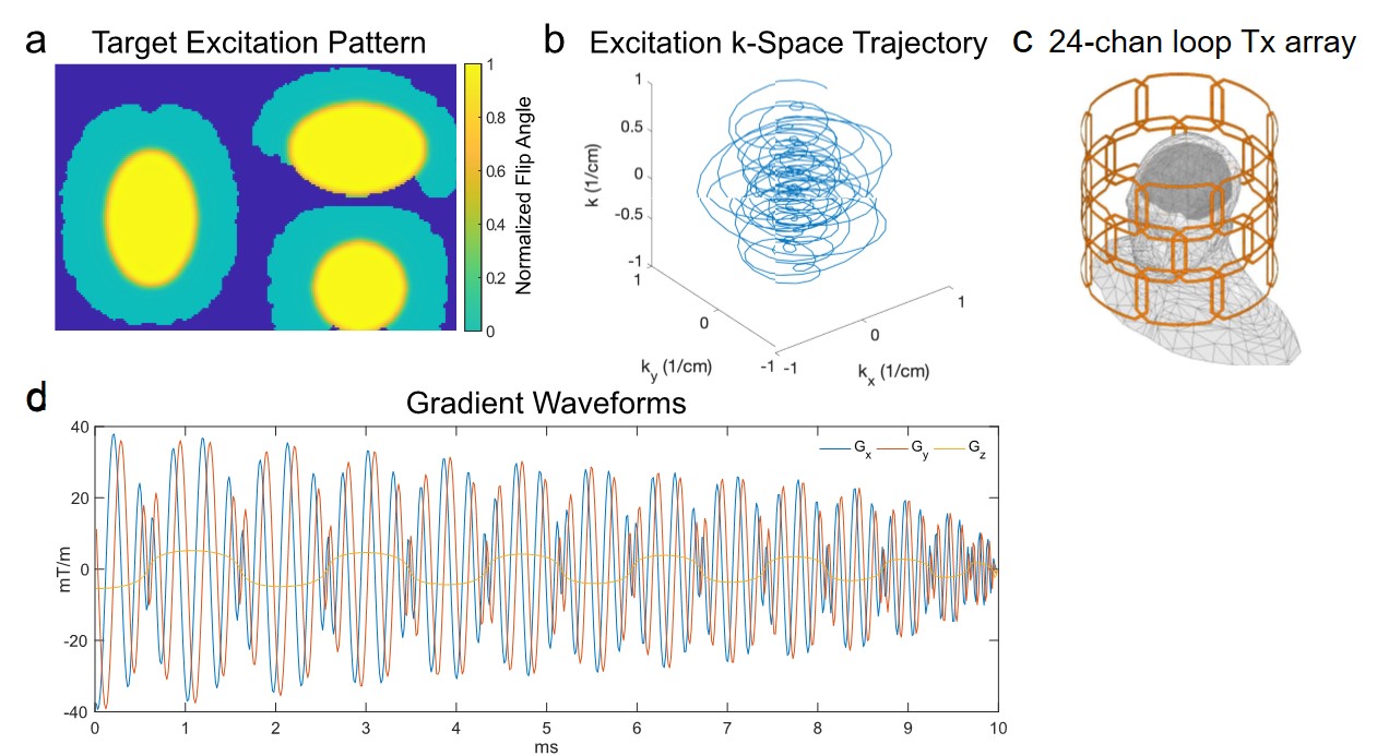
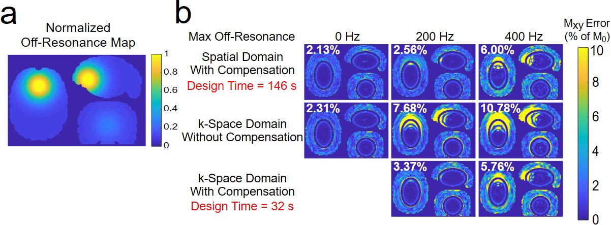
Simulations were performed to validate and characterize the proposed 3D k-space domain pTx pulse design method, with comparisons to a conventional iterative spatial domain design3. Figure 1a shows the target pattern for all pulse designs which comprised an ellipse centered on the ventricles. This choice of target pattern was motivated by imaging applications for a 7T scanner optimized for imaging the human cortex, in which midbrain signals will be saturated for high-resolution, highly-accelerated imaging of the cortex. Pulses were designed to excite the entire ellipse and achieve zero-excitation in voxels in the cerebrum but outside the ellipse. RF pulses were designed for a simulated 24-channel loop transmit array (Figure 1c) that is being built for the scanner, using B1+ maps simulated in a human head model using Ansys HFSS (Canonsburg, PA, USA). The target pattern and the B1+ maps were downsampled from their original 128x128x96 grids (1.5 mm isotropic-resolution) to 64x64x48 grids (3 mm isotropic-resolution), and RF designs were performed with the 64x64x48 grid size. A 10 ms SPINS trajectory7 with 5 mm max resolution was designed for the pulse subject to the scanner’s gradient amplitude and slew rate constraints (Figure 1b&d). For off-resonance compensation, a map (Figure 3a) containing a Gaussian distortion centered above the frontal sinus is incorporated, to mimic air-tissue susceptibility difference-induced B0 inhomogeneity.All pulse designs were performed in MATLAB (Mathworks, Natick, MA, USA). For spatial domain designs, RF pulses were solved using an iterative least-squares conjugate-gradient descent method with 35 iterations. For both design methods, the computation was parallelized using 16 threads without off-resonance compensation incorporated, and 32 threads otherwise. Designs were performed five times for each case, and the mean computation time was recorded. The resulting pulses were Bloch-equation simulated and compared to the target pattern on the finer 128×128×96 grid to capture Gibbs ringing. When calculating excitation errors, the magnitude root-mean-square error (RMSE) was calculated in voxels within the cerebrum, except for an ≈5 mm-thick transition band around the edge of the elliptical target region.
Results
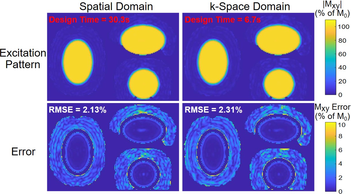
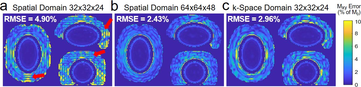
Figure 2 shows simulated excitation patterns and error maps for both designs, with RMSEs of 2.13% (spatial domain) and 2.31% (k-space domain), indicating equally uniform inner volume excitation and intact outer volume. The parallelized k-space domain design decreased the computation time by 78% and reduced the storage requirement by 99%. Figure 3b shows error patterns and RMSEs for both designs, with and without off-resonance compensation, where the correction was successful in both methods with 200 Hz peak amplitude. Figure 7 shows significant Gibbs ringing in the pattern produced by pulses designed by the spatial domain method on a 32×32×24 grid, while Gibbs ringing is not apparent in either the 64×64×48 spatial domain error pattern or the 32×32×24 k-space domain error pattern.Conclusion
The proposed k-space domain algorithm accelerates parallel transmission pulse design. The algorithm also enables compensation of off-resonance which has not previously been described in a k-space domain design. Compared to a spatial domain design, the new algorithm is non-iterative and can be finely parallelized to achieve shorter design times, and can use coarser target grid sizes while avoiding Gibbs ringing. While all the pulse designs in this work used 3D SPINS trajectories, the method can be applied in any number of dimensions and with any excitation k-space trajectory.Acknowledgements
This work was supported by NIH grants R01 EB016695 and U01 EB 025162.References
1. Katscher U, Bornert P, Leussler C, van den Brink JS. Transmit SENSE. Magn Reson Med 2003; 49:144–150.
2. Zhu Y. Parallel excitation with an array of transmit coils. Magn Reson Med 2004; 51:775–784.
3. Grissom WA, Yip CY, Zhang Z, Stenger VA, Fessler JA, Noll DC. Spatial domain method for the design of RF pulses in multicoil parallel excitation. Magn Reson Med 2006; 56:620–9
4. Grissom WA. k-Space domain parallel transmit pulse design. In Proceedings 26th Scientific Meeting, International Society for Magnetic Resonance in Medicine, Paris. 2018; p. 3396.
5. Ma J, Gruber B, Yan X, Grissom WA. k‐Space domain parallel transmit pulse design. Magn Reson Med 2020.
6. Luo T, Noll DC, Fessler JA, Nielsen JF. A GRAPPA algorithm for arbitrary 2D/3D non-Cartesian sampling trajectories with rapid calibration. Magn Reson Med 2019;82:1101–1112.
7. Malik SJ, Keihaninejad S, Hammers A, Hajnal JV. Tailored excitation in 3D with spiral nonselective (SPINS) RF pulses. Magn Reson Med 2012;67:1303–1315.
Figures