3824
A low-cost battery-powered tri-axial current-controlled gradient power supply for sustainable and portable MRI1C.J. Gorter Center for High Field MRI, Leiden University Medical Center, Leiden, Netherlands, 2DEMO, Delft University of Technology, Delft, Netherlands
Synopsis
Low field MRI has gained interest in recent years as a way of providing MRI to under-served and remote settings. MR hardware designed for such applications should be robust, portable and easy to maintain. In this work we present the design of a three-axis gradient amplifier capable of an output current of up to 15 amperes. The gradient amplifier is designed to run off two car batteries and consumes less than 100 watts during imaging. The components in the gradient amplifier are designed to be easily repairable and commonly available.
Introduction
There is increasing interest in the capabilities of low-field MRI, with systems varying in field strength from 0.55 T (1,2) to 50-200 mT (permanent magnet arrays)(3-6) and 0.01T (large homogeneous electromagnets). Permanent magnet systems in the 50-200 mT range have been designed specifically for applications which require portability, with systems ranging in weight from 75 kg (6) to ~500 kg (8,9). As part of making such systems sustainable, the associated electronics such as RF and gradient amplifiers should be as robust as possible with respect to operating conditions, be easily repairable, and ideally be able to run of battery power for operation in remote regions. Recently we described a three-axis current-output gradient amplifier that was used to acquire three-dimensional images on a 50 mT Halbach permanent magnet array (5). In this abstract we describe an improved version of this gradient amplifier which makes it more robust and sustainable.Methods
The system operating at 50 mT (2.15 MHz) has been described in detail previously (6) and has gradients coils with inductances of 180, 225, and 225 mH and resistances of 0.39, 0.41 and 0.42 ohms, respectively. The gradient amplifier is driven by digital-to-analogue (DAC) gradient output boards from a Magritek Kea 2 console (Aachen, Germany), with a voltage range of +/- 10 volt at a 16-bit resolution.Design specifications for the new amplifier were: maximum current to the load +/- 15 Amps, maximum duty cycle 30% per channel, load inductance between 20 and 300 mH, rise time 50 ms which results in a bandwidth of 7 kHz, overload protection, driving a coil with equivalent series resistance 0.4 W and parasitic parallel capacitance between the gradient coils estimated at 130 pF. The amplifier is designed to run off an external power source with a supply voltage between +/- 10.5V and +/- 15V. To facilitate the use of batteries, where the voltage drops as the battery discharges, the biasing of the amplifier is made relative to the relevant power supply rails. When the batteries are drained an under-voltage lock-out disables the amplifiers at a threshold voltage of 10.5 volts. Two 20 Amp car fuses (ATO Blade) are used for protection at the positive and negative terminals. Filters are placed on the power supply lines to reduce noise introduced by the power supplies.
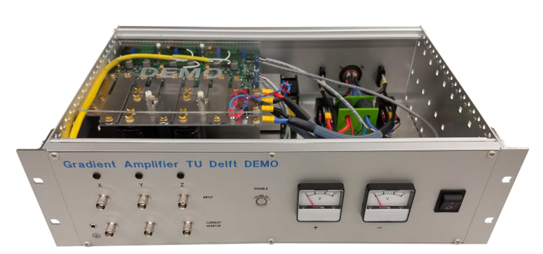
A four layer PCB configuration was designed with each layer designed for a specific purpose: the upper layer 1 had most of the components for easy access, replacement and routing, layer 2 was a ground layer for thermal stability and optimal heat spreading which is separated per channel to prevent cross coupling, layer 3 routes the power and layer 4 contains the high power components with wide copper tracks. The constructed amplifier is shown in Figure 1.
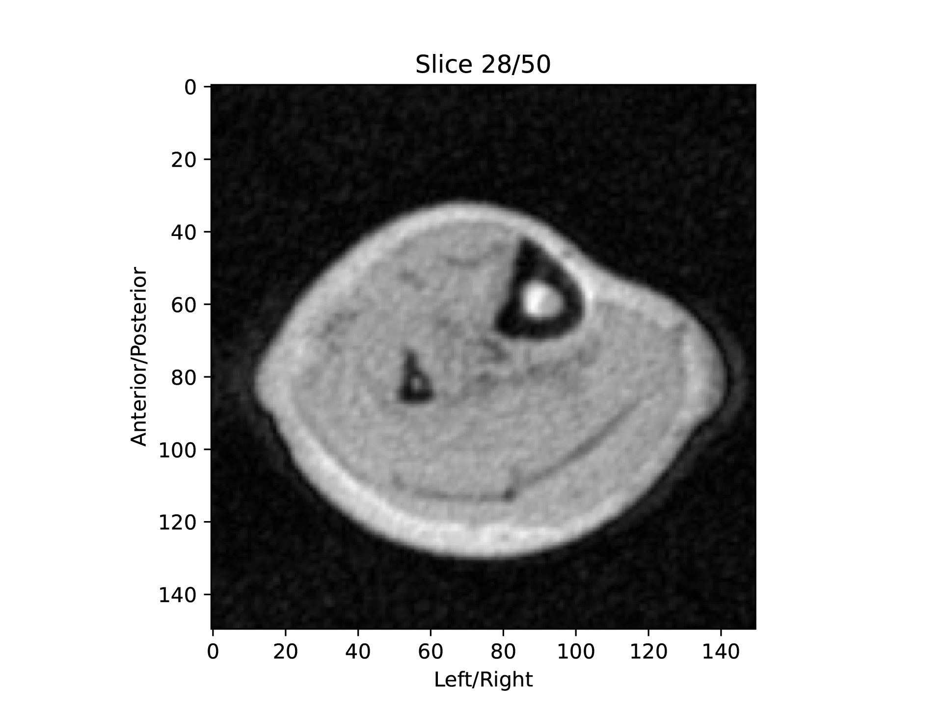
An image of the lower leg was acquired using the gradient amplifier to drive the gradient coils. The image was acquired using a 3D TSE sequence with the following parameters: FoV: 150x150x200 mm, resolution: 1x1x4 mm, TR/TE: 400 ms/8 ms, ETL: 10, acquisition bandwidth: 20 kHz.
Results
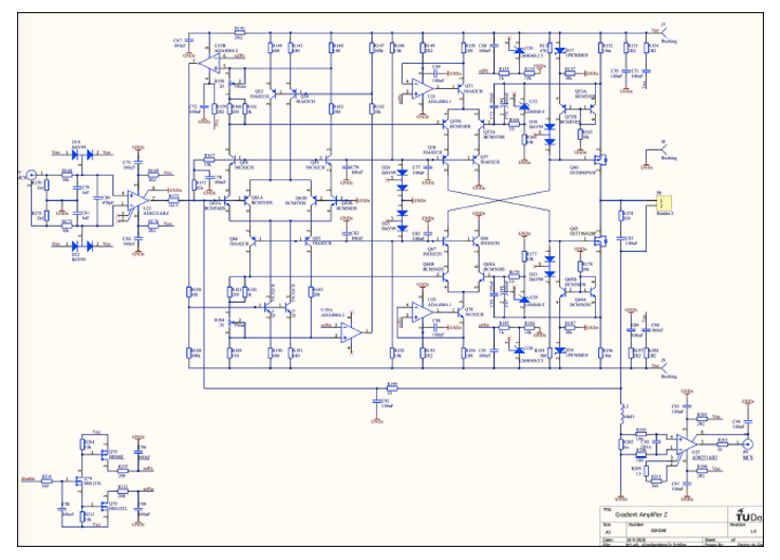
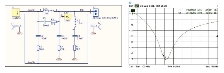
Figure 2 shows a schematic of one of the channels of the improved gradient amplifier (each channel is identical). At a 3A average discharge current, which was typical for an imaging session, the batteries lasted 5-6 hours.At 2 MHz the measured voltage noise on the output noise was -123 dBm/Hz, so roughly 50 dB above thermal noise. Although an RF shield is in place between the gradient coils and the RF coil, this does not provide sufficient attenuation without being extremely thick which introduces significant eddy currents. Notch filters, see Figure 3(a,b), were designed at the gradient amplifier outputs which gave over 40 dB attenuation. Noise measurements performed at 2.15 MHz using an RF coil placed at the center of the system showed no increase in the measured noise by the spectrometer after the gradient amplifiers were switched on.
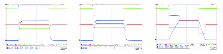
Figure 4 shows the step response of one of the channels when driving an inductance of 213 mH with ESR of 0.32 W. The waveforms show high fidelity at lower driving currents, whereas it is clearly seen that at 15A the output starts to limit the slew rate because of clipping to the supply rail. Figure 5 shows a single coronal slice of the lower leg reconstructed from a 3D dataset.
Discussion
We demonstrate a low-cost highly portable 3 channel gradient amplifier designed for small MRI systems that is capable of running of two 12V batteries. Power consumption during imaging is less than 100 Watts, low enough to easily run off solar power. The PCB is designed to be easily repairable and commonly available components are used wherever possible to improve sustainability further. The gradient amplifier was tested on a small head sized system where we were able to obtain gradient strengths of up to 10 mT/m and a slew rate of 40 T/m/s. The slew rate of the gradient amplifier could be improved by using higher voltage as shown in figure 4 but would require larger power supplies and increased power consumption.Acknowledgements
This work is supported by the following grants: Horizon 2020 ERC FET-OPEN 737180 Histo MRI, Horizon 2020 ERC Advanced NOMA-MRI 670629, Simon Stevin Meester Award and NWO WOTRO Joint SDG Research Programme W 07.303.101.References
1. Bandettini WP,
Shanbhag SM, Mancini C, McGuirt DR, Kellman P, Xue H, Henry JL, Lowery M, Thein
SL, Chen MCY, Campbell-Washburn AE. A comparison of cine CMR imaging at 0.55 T
and 1.5 T. J Cardiovasc Magn R 2020;22(1).
2. Campbell-Washburn AE, Ramasawmy R, Restivo MC, Bhattacharya I, Basar B, Herzka DA, Hansen MS, Rogers T, Bandettini WP, McGuirt DR, Mancini C, Grodzki D, Schneider R, Majeed W, Bhat H, Xue H, Moss J, Malayeri AA, Jones EC, Koretsky AP, Kellman P, Chen MY, Lederman RJ, Balaban RS. Opportunities in Interventional and Diagnostic Imaging by Using High-Performance Low-Field-Strength MRI. Radiology 2019;293(2):384-393.
3. Cooley CZ, Haskell MW, Cauley SF, Sappo C, Lapierre CD, Ha CG, Stockmann JP, Wald LL. Design of Sparse Halbach Magnet Arrays for Portable MRI Using a Genetic Algorithm. Ieee T Magn 2018;54(1).
4. Cooley CZ, McDaniel P, Stockmann J, Srinivas SA, Cauley SF, Sliwiak M, Sappo C, Vaughn CF, Guerin B, Rosen MS, Lev MH, Wald LL. A portable brain MRI scanner for underserved settings and point-of-care imaging. arXiv:200413183 [eessIV] 2020.
5. O'Reilly T, Teeuwisse WM, de Gans D, Koolstra K, Webb AG. In vivo 3D brain and extremity MRI at 50 mT using a permanent magnet Halbach array. Magn Reson Med 2020.
6. O'Reilly T, Teeuwisse WM, Webb AG. Three-dimensional MRI in a homogenous 27 cm diameter bore Halbach array magnet. J Magn Reson 2019;307.
7. Sarracanie M, LaPierre CD, Salameh N, Waddington DEJ, Witzel T, Rosen MS. Low-Cost High-Performance MRI. Sci Rep-Uk 2015;5.
8. He Y, He W, Tan L, Chen F, F. M, Feng H, Xu Z. Use of 2.1 MHz MRI scanner for brain imaging and its preliminary results in stroke. J Magn Reson 2020;319:106829.
9. Sheth KN, Mazurek MH, Yuen MM, Cahn BA, Shah JT, Ward A, Kim JA, Gilmore EJ, Falcone GJ, Petersen N, Gobeske KT, Kaddouh F, Hwang DY, Schindler J, Sansing L, Matouk C, Rothberg J, Sze G, Siner J, Rosen MS, Spudich S, Kimberly WT. Assessment of Brain Injury Using Portable, Low-Field Magnetic Resonance Imaging at the Bedside of Critically Ill Patients. Jama Neurol 2020.
Figures