3759
Creation of a four-dimensional numerical phantom for Bloch simulations of water-fat systems1MRIsimulations Inc., Tokyo, Japan, 2University of Tsukuba, Tsukuba, Japan
Synopsis
A four-dimensional (4D) numerical phantom, which is defined by the three-dimensional (3D) spatial axes and the resonance frequency axis, is indispensable for Bloch simulations of protons in biological tissues with complex distribution of materials. In this study, a 4D phantom was created using an image dataset of an actual biological sample containing water and fat, and the Bloch simulation was performed using the phantom. As a result, 3D images of the samples containing water and fat were successfully reproduced, which demonstrated the usefulness of the concept of the proposed 4D phantom.
Introduction
We have recently reported a method to perform Bloch simulations of biological samples with chemical shift and T2* distributions1. In this method, a numerical phantom, i.e., proton density (PD), T1 and T2 in a four-dimensional (4D) space with spatial three-dimensional axes and a resonance frequency axis is used for the Bloch simulation. In the previous report, we demonstrated the usefulness of this approach using test tubes filled with doped water, peanut oil, margarine, and sausage. The problem in the previous study, however, was that each material was spatially separated, and the effectiveness of the approach was not fully demonstrated. In this paper, we report a method for creating a 4D numerical phantom including different materials (e.g. water and fat) coexist in a voxel.Materials and methods
A commercially available pork block bacon was used for the imaging experiment to create a 4D numerical phantom (Fig. 1(a)). To prevent the sample from drying, the bacon was inserted into a 48 mm diameter plastic bottle for imaging. For the imaging experiments, we used an original MRI system with a 1.5 T superconducting magnet (JMTB-1.5/280/SSE, JASTEC, Kobe, Japan), which has a horizontal room temperature aperture of 280 mm in inner diameter, and a digital MRI console (MRTechnology, Tsukuba, Japan). For the 3-axis gradient coil set, a self-made gradient coil set with an inner diameter of 87 mm was used. The RF coil was a 64 mm diameter, 64 mm long, 8-element birdcage coil of our own design. Pulse sequences were 3D spin echo sequences with TR/TE = 800 ms/20 ms (PDW), 160 ms/20 ms (T1W), and 800 ms/40 ms (T2W) (FOV: 64 mm × 64 mm × 128 mm, image matrix: 128 × 128 × 512, voxel size: 0.5 mm × 0.5 mm × 0.25 mm). In order to obtain water-fat images using the Dixon method2,3, the spin echo refocusing time was shifted by ±2.2 ms from the original spin echo refocusing time in the parameter weighted sequences. The images with 128 cube matrices in the 64 mm cubic FOV area in the center of the sample were used to create a 4D numerical phantom (Fig. 1(a)).To separate the water and fat images, the standard 3-point Dixon method3 was used, as shown in Fig.1(b). However, to remove the phase aliasing caused by the static field inhomogeneity, the inhomogeneity field was estimated from the phase images and virtual magnetic field shimming was performed instead of phase unwrapping. Using the magnetic field inhomogeneity estimated by this method, water-fat images in PDW, T1W, and T2W images were created, and the PD, T1, and T2 maps of water and fat were calculated using the parameter weighted images. Using the parameter maps, a 4D numerical phantom was created, and a fast Bloch simulator (BlochSolver)4,5 was used to simulate the 3D spin echo sequences used in the Dixon method.
Results
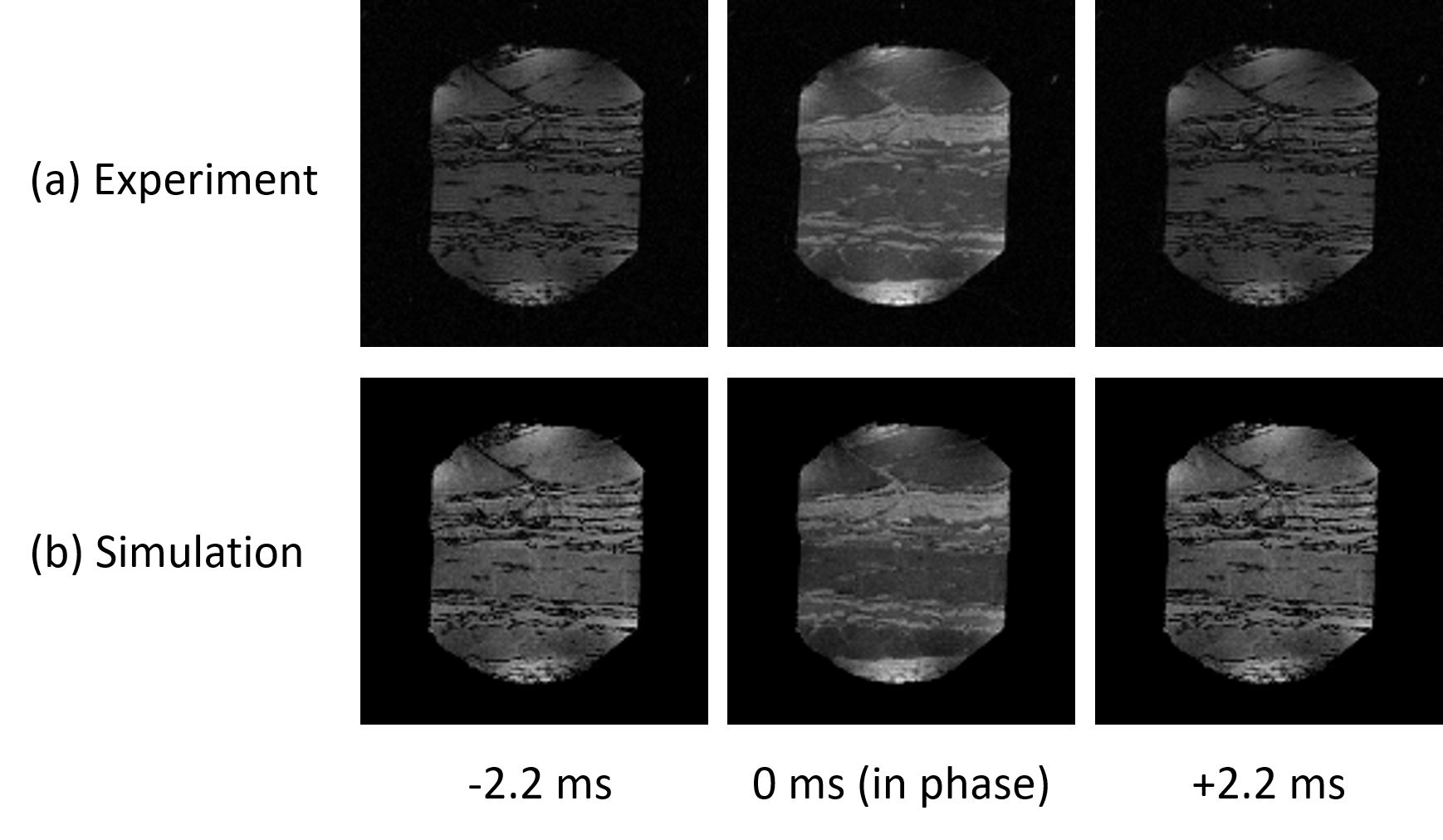
Following the method shown in Fig.1(b), water-fat separation was performed on the central 16 axial planes (8 mm thick). Fig.2(a) shows one cross-section of the PDW, T1W, and T2W images created by the method, in which water and fat were separated. Fig.2(b) shows the PD, T1, and T2 maps calculated from the separated parameter weighted images shown in Fig.2(a) using the standard spin-echo signal intensity formula. The concept of the 4D numerical phantom using these parameter maps is shown in Fig.3. Although seven major resonance lines were observed for fat, for simplicity in this study, we assumed that fat had one resonance line. However, since some fat resonance line with an intensity of a few percent existed near the water resonance line, the fat distribution was mixed in the frequency-separated water image.Fig.4(a) shows the central cross-sectional PDW images acquired in the experiment, and Fig.4(b) shows the corresponding PDW images obtained by the simulation of the 4D numerical phantom shown in Fig.3. The simulated images were obtained by simulating the 3D water phantom in a uniform static magnetic field corresponding to -114 Hz, and the 3D fat phantom in a uniform static magnetic field corresponding to +114 Hz. After adding the two sets of the simulated signal, the images shown in Fig.4(b) were reconstructed. The experimental and simulated images were in good agreement, although there were some differences.
Discussion
The good agreement between the experimental images and the simulated images shown above demonstrated that the phantom creation method used in this study was reasonable. The minor differences can be attributed to the median and the low pass filters used to suppress the image noise generated by the error in the calculation process of the water and fat separation. In addition, white noise was superimposed on the experimental images, and this noise contributed to the image differences. Therefore, it is important to suppress the noise as much as possible in order to obtain a better phantom for the Bloch simulation.In conclusion, it is suggested that the concept of the 4D phantom proposed in the previous study is useful for the Bloch simulation in actual biological systems.
Acknowledgements
No acknowledgement found.References
[1] Kose R, Kose K, Terada Y, Tamada D, Motosugi U. Development of a method for the Bloch image simulation of biological tissues. Magn Reson Imaging. 2020 Dec;74:250-257.
[2] Dixon WT. Simple proton spectroscopic imaging. Radiology 1984;153:189 –194.
[3] Glover GH, Schneider E. Three-point Dixon technique for true water/fat decomposition with B0 inhomogeneity correction. Magn Reson Med 1991;18:371–383.
[4] Kose R, Kose K. BlochSolver: A GPU-optimized fast 3D MRI simulator for experimentally compatible pulse sequences. J Magn Reson 2017;281: 51–65.
[5] Kose R, Setoi A, Kose K. A fast GPU-optimized 3D MRI simulator for arbitrary k-space sampling. Magn Reson Med Sci, 2019;18: 208–218.
Figures