3755
Investigation of TES Simulation Sensitivity to Skull Simplification using a Multimodal MR-Based Detailed Head Model1Electrical and Computer Engineering Department, Worcester Polytechnic Institute, Worcester, MA, United States, 2Center for Devices and Radiological Health, US Food and Drug Administration, Silver Spring, MD, United States, 3Athinoula A Martinos Center for Biomedical Imaging, Massachusetts General Hospital, Harvard Medical School, Boston, MA, United States
Synopsis
One of the most detailed multimodal human head models currently available (MIDA, 0.5 mm isotropic res., 100+ compartments) is accurately analyzed numerically to investigate the effects of the fine structure of the skull on transcranial electrical stimulation (TES). A simplified case, where the diploë and dura are treated as cortical bone, is compared against the full-model case. For each electrode in a 10-10 configuration, coefficients are computed independently to scale the cortical fields from the simplified case to match the cortical fields from the realistic case, investigating the topological field differences in the process.
Introduction
Versatile electromagnetic modeling packages applied to transcranial electrical stimulation (TES) – Sim4Life1 and SimNIBS2 – rely on the finite difference method (FDM) or finite element method (FEM), respectively, to model the electric fields induced in the brain by a given stimulation setup. The resolution and level of detail of the simulated head models is inherently constrained by limitations of the FEM solver in use, by resolution of MR and other medical imaging data, and by limitations of segmentation tools applied to that data. Default datasets produced by the SimNIBS 2.1-3.1 pipeline, for instance, comprise the following tissues: white matter (WM), gray matter (GM), cerebrospinal fluid (CSF), bone, and scalp3,4,5. If these models account for the effects of cancellous bone in the skull, they do so by adjusting the overall skull conductivity6. Using the extremely high-resolution MIDA model and a non-FEM-based solver, we investigate the effect of this simplifying assumption on the fields induced by TES in the cortex.Background
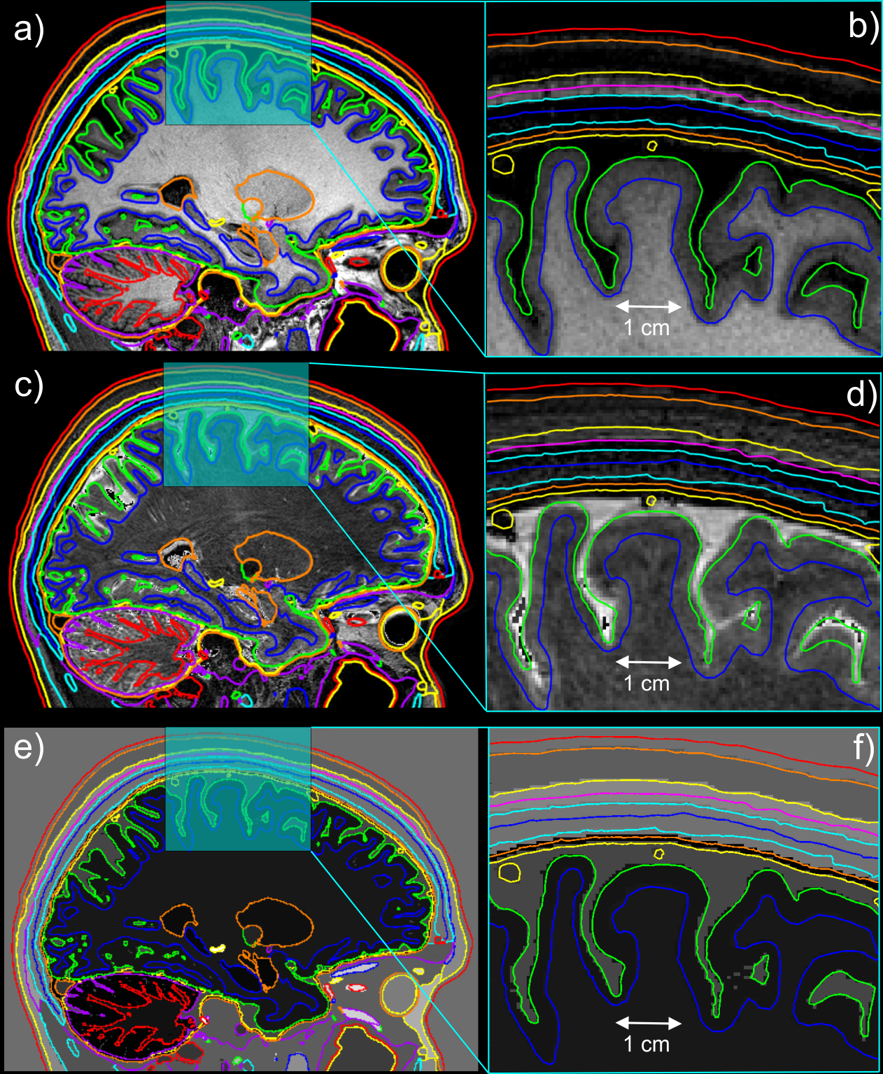
The Boundary Element Fast Multipole Method (BEM-FMM) formulation is based on surface charges that accumulate between conducting media of different conductivities. Rather than filling media volumes with hexahedra or tetrahedra, the BEM-FMM operates directly on triangular surface meshes that describe the boundaries between adjoining tissues. Observation points for electric fields, current density, and other quantities are unconstrained by FEM volumetric resolution and may be placed at arbitrary locations throughout the model7.The MIDA model, developed by Iacono et al8, is one of the most detailed (perhaps the most detailed) human head models currently available4. The surface model was constructed from 0.5 mm isotropic MRI data and has more than 11 M (closely spaced) facets, enabling accurate segmentation of the epidermis/dermis, subcutaneous adipose tissue, outer (cortical) skull, skull diploë (cancellous skull), inner (cortical) skull, dura mater, cerebrospinal fluid, gray matter, and white matter (in addition to separate cerebellum gray matter and cerebellum white matter segmentations)8. Sagittal cross-sections of the MIDA model are shown in Figure 1.
Methods
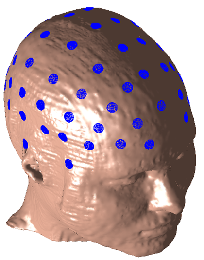
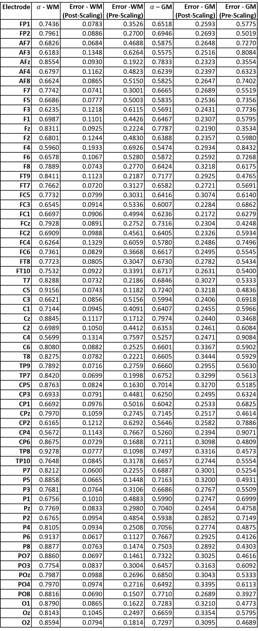
An approximate 10-10 configuration of electrodes was imprinted on the MIDA model’s epidermis mesh as shown in Figure 2. For each electrode in the configuration, the total electric field was computed just inside all gray matter facets and just outside all white matter facets when that electrode was assigned a potential of 1 V and all other electrodes were assigned a potential of 0 V. This set of 64 full E-field solutions was computed for the following cases: the base case, where the diploë and dura were treated as independent tissues, and the simplified case, where the diploë and dura were both treated as cortical bone.For each electrode of the 10-10 configuration, an attempt was made to find a corrective scalar $$$\alpha$$$ that would map that electrode’s associated E-field as evaluated in the simplified case to its E-field as evaluated in the base case. Mathematically, the goal was to select $$$\alpha$$$ to minimize the error expression $$$\parallel \alpha Q_{test} - Q_{base} \parallel/\parallel Q_{base} \parallel$$$ , where $$$Q_{test}$$$ denotes the vector of a selected field quantity evaluated at every WM/GM facet for the simplified skull case, $$$Q_{base}$$$ denotes the equivalent field quantity for the base case, and $$$\parallel \cdot \parallel$$$ denotes the vector 2-norm over all facets. The field quantities $$$Q$$$ evaluated were the following: the total E-field magnitude evaluated just outside the white matter surface ($$$\mid E_{WM} \mid$$$) and the total E-field magnitude evaluated just inside the gray matter surface ($$$\mid E_{GM} \mid$$$). Here, $$$\mid \cdot \mid $$$ denotes the vector 2-norm of the specified field quantity at a single facet.
Results
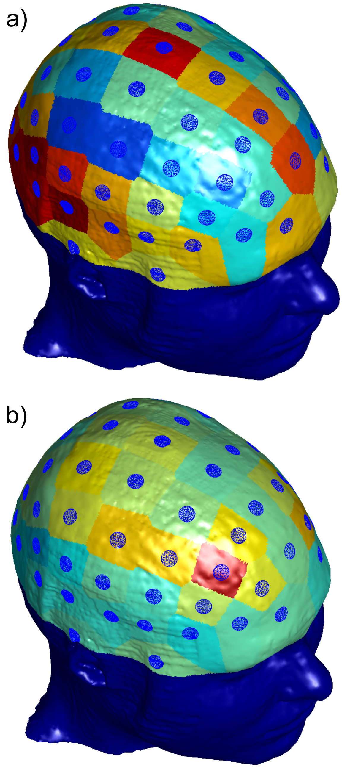
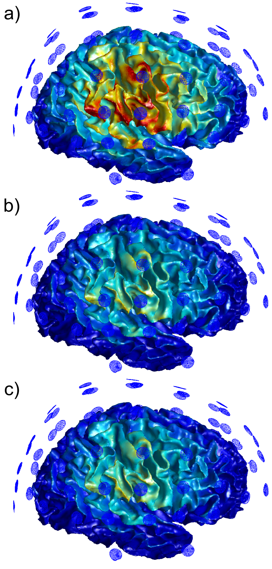
For each of the electrodes in the 10-10 configuration, the value of $$$\alpha$$$ and associated error expression were evaluated for each aforementioned field quantity. Values for the total field magnitude have been tabulated in Figure 3 and visualized in Figure 4. Figure 5 shows the E-field magnitude induced just outside the WM surface by electrode C4 for the simplified case, the scaled simplified case, and the base case.On a server with a 32-core, 2.1 GHz Intel Xeon E5-2683 v4 CPU and 256 GB of RAM running Windows Server 2019 and MATLAB r2020a, the electric field solution for each electrode took 12 minutes to compute using the BEM-FMM.
Discussion
The method of scaling the E-field from a simplified skull model on a per-electrode basis may be useful for estimating fields that occur at the white matter surface due to a given electrode configuration. Further, the regional variations in the value of the per-electrode optimal field scalar suggest that it may not be appropriate to apply a single scalar to the total field produced by all electrodes, unless all active electrodes in question already share similar individual optimal scalar values. Since almost all field errors for the gray matter surface reach or exceed 25% even after correction by per-electrode scalars, the field at the gray matter surface should probably not be approximated in this manner. This analysis is only possible because of the high resolution of the MIDA model, and further investigation with a larger set of similarly detailed head models is required to confirm this result and support subsequent research.Acknowledgements
The mention of commercial products, their sources, or their use in connection with material reported herein is not to be construed as either an actual or implied endorsement of such products by the Department of Health and Human Services.References
1. Sim4Life. Zurich Med Tech. Accessed December 10, 2020. Online: https://www.zurichmedtech.com/sim4life/
2. Saturnino GB, Madsen KH, And Thielscher A. “Electric field simulations for transcranial brain stimulation using FEM: an efficient implementation and error analysis”. Journal of Neural Engineering. 2019 Nov. 6; 16(6). doi: 10.1088/1741-2552/ab41ba
3. Htet AT, Burnham EH, Noetscher GM, Pham DN, Nummenmaa A, Makarov SN. “Collection of CAD human head models for electromagnetic simulations and their applications”. Biomed. Phys. Eng. Express. 2019 Nov. 1; 5(6): 067005. doi: 10.1088/2057-1976/ab4c76
4. Farcito S, Puonti O, Montanaro H, Saturnino GB, Nielsen JD, Madsen CG, Siebner HR, Neufeld E, Kuster N, Lloyd BA. "Accurate anatomical head segmentations: a data set for biomedical simulations," 2019 41st Annual International Conference of the IEEE Engineering in Medicine and Biology Society (EMBC), Berlin, Germany, 2019, pp. 6118-6123, doi: 10.1109/EMBC.2019.8857041.
5. Puonti O, Van Leemput K, Saturnino GB, Siebner HR, Madsen KH, Thielscher A. “Accurate and robust whole-head segmentation from magnetic resonance images for individualized head modeling”. NeuroImage, 2020 October; 219. doi: 10.1016/j.neuroimage.2020.117044
6. McCann H, Pisano G, and Beltrachini L. “Variation in Reported Human Head Tissue Electrical Conductivity Values”. Brain Topography, 2019 May 3; 32. doi: 10.1007/s10548-019-00710-2
7. Makarov SN, Noetscher GM, Raij T, and Nummenmaa A. "A Quasi-Static Boundary Element Approach With Fast Multipole Acceleration for High-Resolution Bioelectromagnetic Models”. IEEE Transactions on Biomedical Engineering. 2018 Dec; 65(12); pp. 2675-2683. doi: 10.1109/TBME.2018.2813261.
8. Iacono MI, Neufeld E, Akinnagbe E, Bower K, Wolf J, Oikonomidis IV, Sharma D, Lloyd B, Wilm BJ, Wyss M, Pruessmann KP, Jakab A, Makris N, Cohen ED, Kuster N, Kainz W, and Angelone LM. “MIDA: A Multimodal Imaging-Based Detailed Anatomical Model of the Human Head and Neck”. PLOS One. 2015 Apr. 22; 10(4): e0124126. doi: 10.1371/journal.pone.0124126
Figures