3636
A Comparison of Metal Artifacts in Cardiovascular MRI at 0.55T and 1.5T
W. Patricia Bandettini1, Christine Mancini2, Sujata M. Shanbhag2, Jennifer Lynn Henry2, Margaret M. Lowery2, Marcus Y. Chen2, and Adrienne E. Campbell-Washburn2
1NIH/NHLBI, Bethesda, MD, United States, 2NATIONAL INSTITUTES OF HEALTH/NHLBI, BETHESDA, MD, United States
1NIH/NHLBI, Bethesda, MD, United States, 2NATIONAL INSTITUTES OF HEALTH/NHLBI, BETHESDA, MD, United States
Synopsis
Low-field MRI may offer reduced artifacts in patients with implanted metallic devices. In this early comparison, we sought to evaluate the appearance of artifacts seen on cardiac MR at a 0.55T versus 1.5T for common cardiovascular devices, including sternal wires, valves, surgical clips, and cardiac implantable electronic devices (CIEDs). For smaller discrete implants, the artifact profile was reduced at 0.55T, as expected. Whereas, CIED generators contributed significant artifacts at both field strengths, illustrating the complex relationship with material properties, sequence details and field strength. Overall, lower field may offer some advantage for cardiac imaging of patients with common implanted devices.
INTRODUCTION
Lower field strength MRI combined with modern hardware, acquisition methods and reconstruction methods has recently become a topic of increasing interest for cardiac magnetic resonance (CMR) (1, 2). One area of potential benefit is the imaging of patients with implanted metallic devices, which continues to be a challenge for conventional CMR imaging due to severe susceptibility artifacts. Devices can include sternal wires, valves, surgical clips and bypass graft markers, septal occluders, as well as cardiac implantable electronic devices (CIEDs) such as pacemakers, defibrillators and loop recorders. Although absolute susceptibility reduces linearly with field strength, artifact size of metallic implants demonstrates a more complex relationship with material properties, orientation relative to B0, and sequence type/parameters (3). In this early observational comparison, we sought to evaluate the appearance of implanted metal seen on CMR at a 0.55T field strength compared to 1.5T.METHODS
Subjects (n = 11) with one or more known implants underwent imaging on both a prototype 0.55T scanner and clinical 1.5T scanner (both MAGNETOM Aera, Siemens Healthineers, Erlangen, Germany). Artifact size was compared qualitatively between field strengths in similar views on a steady state free precession sequence. For the patients with right ventricular leads that could be visualized in cross-section, measurements of lead diameter were performed. bSSFP imaging generates artifacts that are a combination of “blooming” susceptibility artifacts and banding. Sequence parameters were independently optimized for each field strength, and therefore were not matched (4). Gradient recalled echo (GRE) cine imaging was used in one patient with CIED to minimize artifact from the generator.RESULTS
We imaged patients with bioprosthetic valves (4), sternal wires (4), defibrillators (2), loop recorders (2), pacemakers (2), Amplatz septal occluder (1), aortic bypass graft marker (1) and vertebral rods (1). Implanted metallic devices caused susceptibility artifacts visible at both field strengths, but the artifact profile for all devices was more prominent at 1.5T, as expected. Figures 1, 2 and 3 compare artifact size for a patient with post-surgical implants (sternal wires, bioprosthetic valve, and aortic bypass graft marker). These images demonstrate the relative reduction in blooming artifact and banding between 1.5T and 0.55T on bSSFP imaging. For example, the metallic valve ring artifact (Figure 3), measured in the cross section (linear dimension across the valve ring wall), reduced from 6.1mm at 1.5T to 2.6mm at 0.55T. Figure 4 illustrate examples CIED generators imaged with bSSFP and GRE in two different patients. In these patients, the generator contributed significant artifacts at both field strengths, whereas the pacing leads produced smaller artifacts at 0.55T. For the four right ventricular lead cross-sectional measurements, lead diameters were consistently larger at 1.5T compared to the 0.55T diameters (1.5T vs.0.55T diameters: 8.3 vs. 6.6 mm; 6.1 vs. 2.6 mm; 12.8 vs.6 mm, and 7.0 vs. 4.4 mm). Figure 5 demonstrates lead artifacts in two patients and illustrates reduced artifact at 0.55T and limited dephasing of blood as it flows by the leads.DISCUSSION
Most metallic and implant artifacts decreased at the lower field strength of 0.55T, as expected; however, the artifact reduction varied based on device specifications and material properties. Quantitative assessment of artifact size from 2D imaging for comparison between 0.55T and 1.5T is challenging and was not pursued here. Most medical metallic implants are made from paramagnetic materials, but some stainless steels can be saturated at clinically-relevant field strengths (5), meaning artifact size may not change between 0.55T and 1.5T. Notably, the dense, heavy CIED generator artifacts created significant susceptibility artifacts on both 0.55T and 1.5T field strengths; whereas smaller discrete implants uniformly showed less artifact at 0.55T.CONCLUSION
These early observational findings suggest that lower field strength CMR may lend some advantage in decreasing the susceptibility artifact that may be seen with implanted metallic devices and CIEDs. Additional work to characterize the full array of implanted metal artifacts is ongoing.Acknowledgements
Acknowledgements: The authors would like to acknowledge the assistance of Siemens Healthcare in the modification of the MRI system for operation at 0.55T under an existing cooperative research agreement (CRADA) between NHLBI and Siemens Healthcare. We also thank Delaney McGuirt and Kendall O’Brien for their technical support and patient care.References
REFERENCES 1. Campbell-Washburn AE, Ramasawmy R, Restivo MC, Bhattacharya I, Basar B, Herzka DA, et al. Opportunities in Interventional and Diagnostic Imaging by Using High-performance Low-Field-Strength MRI. Radiology. 2019:190452. 2. Simonetti OP, Ahmad R. Low-Field Cardiac Magnetic Resonance Imaging: A Compelling Case for Cardiac Magnetic Resonance's Future. Circ Cardiovasc Imaging. 2017;10(6). 3. Lee M-J, Kim S, Lee S-A, Song H-T, Huh Y-M, Kim D-H, et al. Overcoming Artifacts from Metallic Orthopedic Implants at High-Field-Strength MR Imaging and Multi-detector CT. RadioGraphics. 2007;27(3):791-803. 4. Bandettini WP, Shanbhag SM, Mancini C, McGuirt DR, Kellman P, Xue H, et al. A comparison of cine CMR imaging at 0.55 T and 1.5 T. J Cardiovasc Magn Reson. 2020;22(1):37. 5. Peeters JM, van Faassen EE, Bakker CJ. Magnetic resonance imaging of microstructure transition in stainless steel. Magnetic resonance imaging. 2006;24(5):663-72.Figures
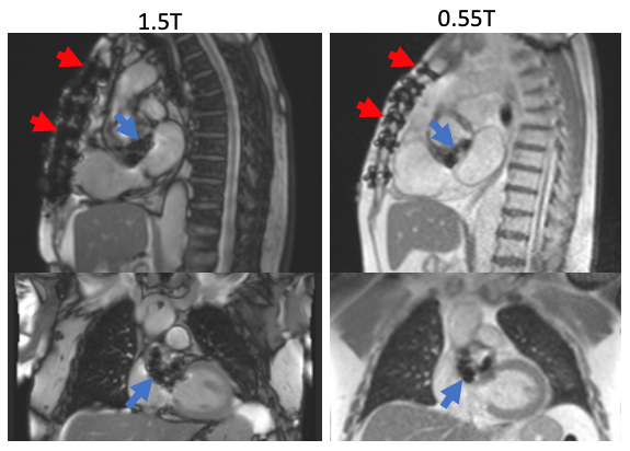
Figure 1. Sternal wire and bioprosthetic aortic valve
artifact appear more prominent at 1.5T (left) compared to 0.55T field strength
(right).
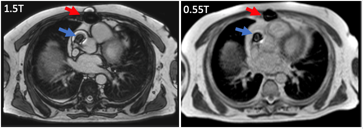
Figure 2. Patient with sternal wire (red arrow) and aortic
bypass graft marker (blue arrow). Both implants appear smaller in size at 0.55T
(right) compared to the 1.5T image (left).
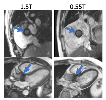
Figure 3. Patient with bioprosthetic valve implant imaged
at 1.5T and 0.55T. The artifact from the valve ring, measured in the
cross-section (linear dimension of the ring thickness), was 6.1 mm at 1.5T
compared with 2.6 mm at 0.55T.
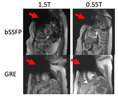
Figure 4. Example images from two patients with CIEDs
imaged at 0.55T and 1.5T; a defibrillator generator imaged with bSSFP
localizers is shown in the top row, and a defibrillator imaged with GRE in a
short-axis left ventricular view is shown in the bottom row. The CIED generators
create a large disruptive imaging artifact at both field strengths and with
both sequences.
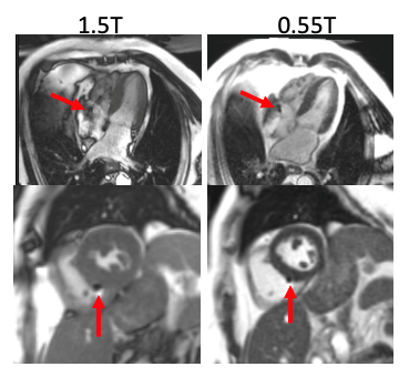
Figure 5. Example pacemaker leads for two patients (4-chamber
on top, short-axis ventricle on bottom) imaged at 1.5T and 0.55T. The artifact
caused by the lead implants was reduced at 0.55T. In addition, the de-phased
blood artifact visible in the 4-chamber view at 1.5T is diminished at 0.55T.