3589
Transportable hyperpolarized glucose: protocol for sample extraction and delivery1LIFMET, EPFL, Lausanne, Switzerland, 2Health Technology, Technical University of Denmark, Kgs. Lyngby, Denmark
Synopsis
Our vision is to make it possible to deliver hyperpolarized compounds to MR facilities that currently have no access to hyperpolarization technology. Today this is not the case and represents hyperpolarized-MR via dissolution Dynamic Nuclear Polarization (dDNP) main shortcoming. The reason is intrinsic in the technique and deals with the presence, in the dDNP sample, of organic free radicals necessary to generate the hyperpolarization. Herein, we demonstrate, for the first time, transportation at cryogenic temperature and remote dissolution of hyperpolarized glucose. The core idea of this project is to exploit the non-persistency of UV-induced radicals for dDNP.
Introduction
Although hyperpolarized (HP) 13C MRI via dissolution Dynamic Nuclear Polarization (dDNP) has the potential to revolutionize diagnostic radiology, giving easier access to personalized treatments [2], this technique struggles in developing into widespread clinical use. The main reason is the striking unbalance between samples throughput and duration of the hyperpolarized state. If creating one single injectable dose of Metabolic Contrast Agents (MCAs) can take hours, after dissolution and extraction from the polarizer, the MCA’s half-life is linked to the 13C nuclear spins longitudinal relaxation time (T1) in the liquid state. The hyperpolarized MCAs signal can be exploited during a time interval no longer than 1 – 2 minutes. Today, equipping an MR facility with hyperpolarization means to install a dDNP polarizer as close as possible to each MR scanner. The latter represents a challenge from both the financial and technical point of view. MCAs relaxation times are several orders of magnitude longer when kept frozen at cryogenic temperature and moderate magnetic field (> 100 mT) allowing, in principle, transportation far away from the production site [3]. Unfortunately, a “traditional” dDNP sample cannot be extracted from the polarizer in the solid-state without losing its hyperpolarization [4]. The culprits are the same free radicals added to the sample to allow the DNP process to happen inside the polarizer [5]. UV-induced non-persistent radicals can represent a workaround [6]. In this study we pushed this idea to the next level moving from a proof-of-principle experiment to a robust protocol that allowed us to demonstrate, for the first time, transport at cryogenic temperature of HP glucose and its dissolution and injection far away from the production site.Methods
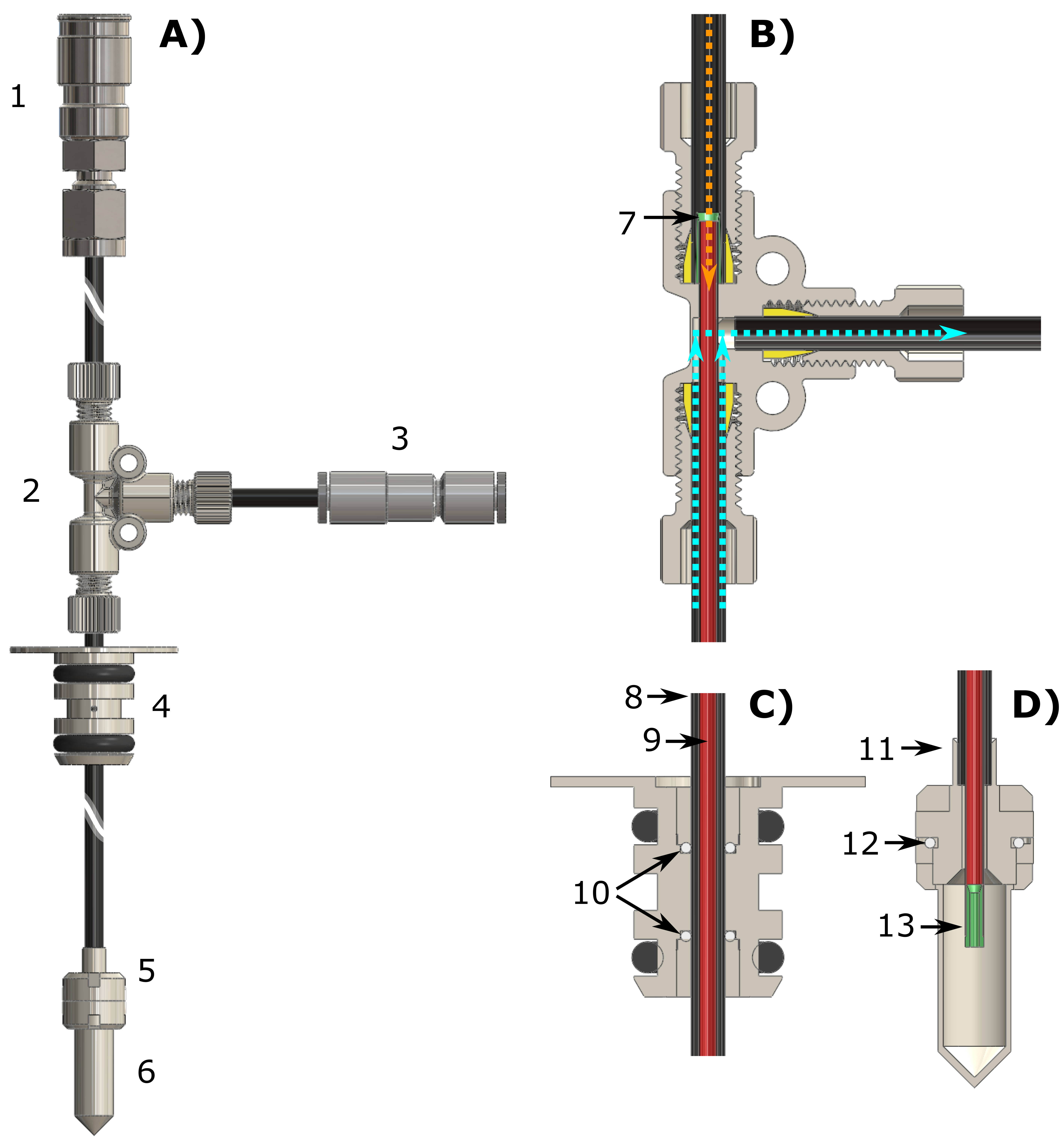
We worked with one single dDNP UV-sample formulation involving [13C6,1,2,3,4,5,6,6-d7]-D-glucose as MCA (2.2 M) and deuterated trimethylpyruvic acid (0.7 M) as radical-precursor [7]. DNP was performed at 6.7 T and 1.2 K using a dDNP polarizer conceptually similar to the idea introduced in 2003 [1], but equipped with a sample loading chamber/air-lock module and a gate valve to be compatible with the fluid path technology [8, 9]. Microwave irradiation was always performed at optimal conditions (i.e. modulating the output frequency by 25 MHz around the central value of 188.21 GHz).In Figure 1 we report the key technological development of this study: the Custom Fluid Path (CFP). The latter allowed us to load the sample inside the polarizer; scavenge the UV-radicals by blowing He gas on the sample to warm it up above 190 K; extract the sample from the polarizer; store it in a transportation device operating at 1 T and 77 K; and finally collect the HP MCA in solution far away from the production site by connecting the CFP to compact dissolution station.
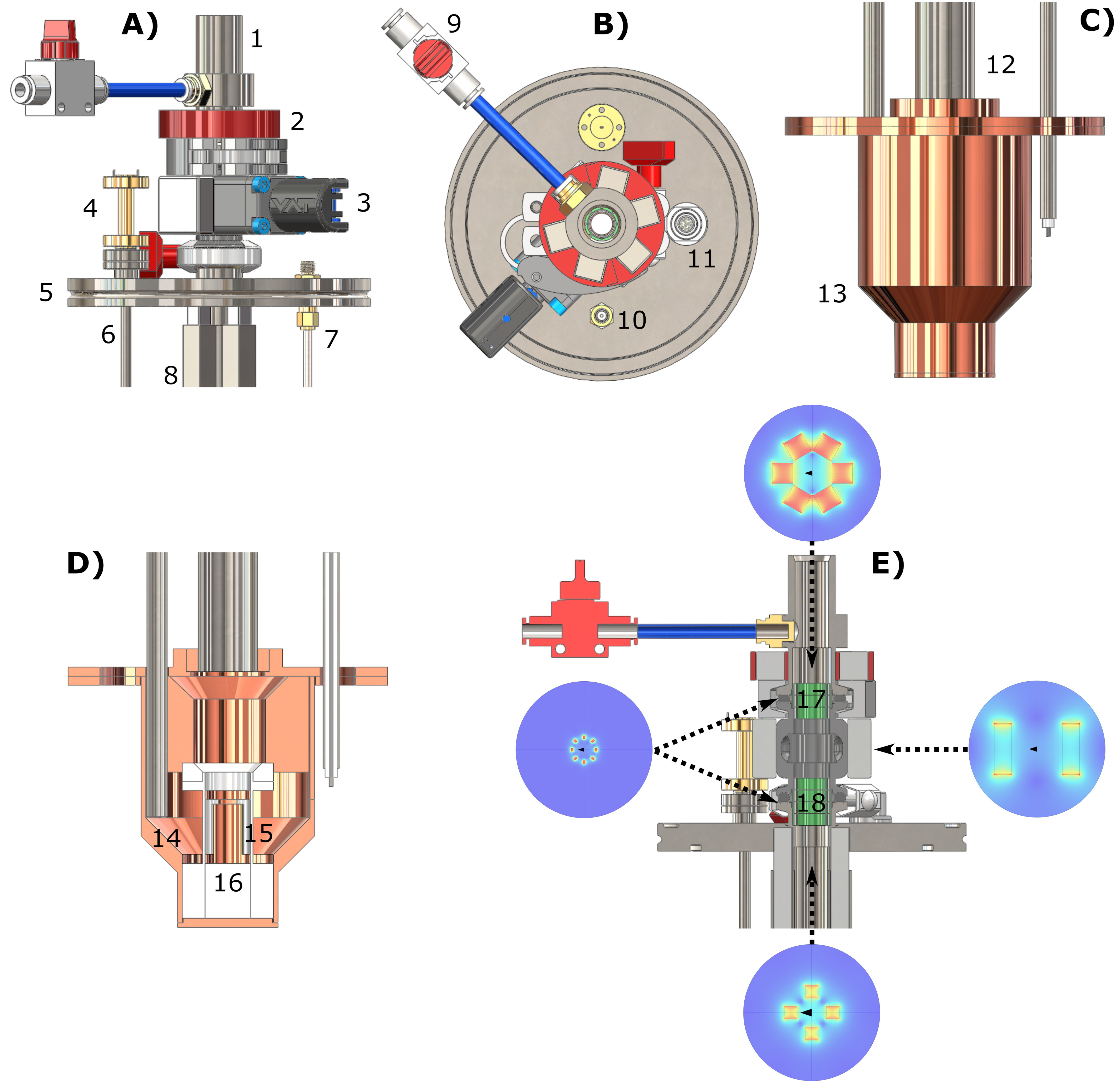
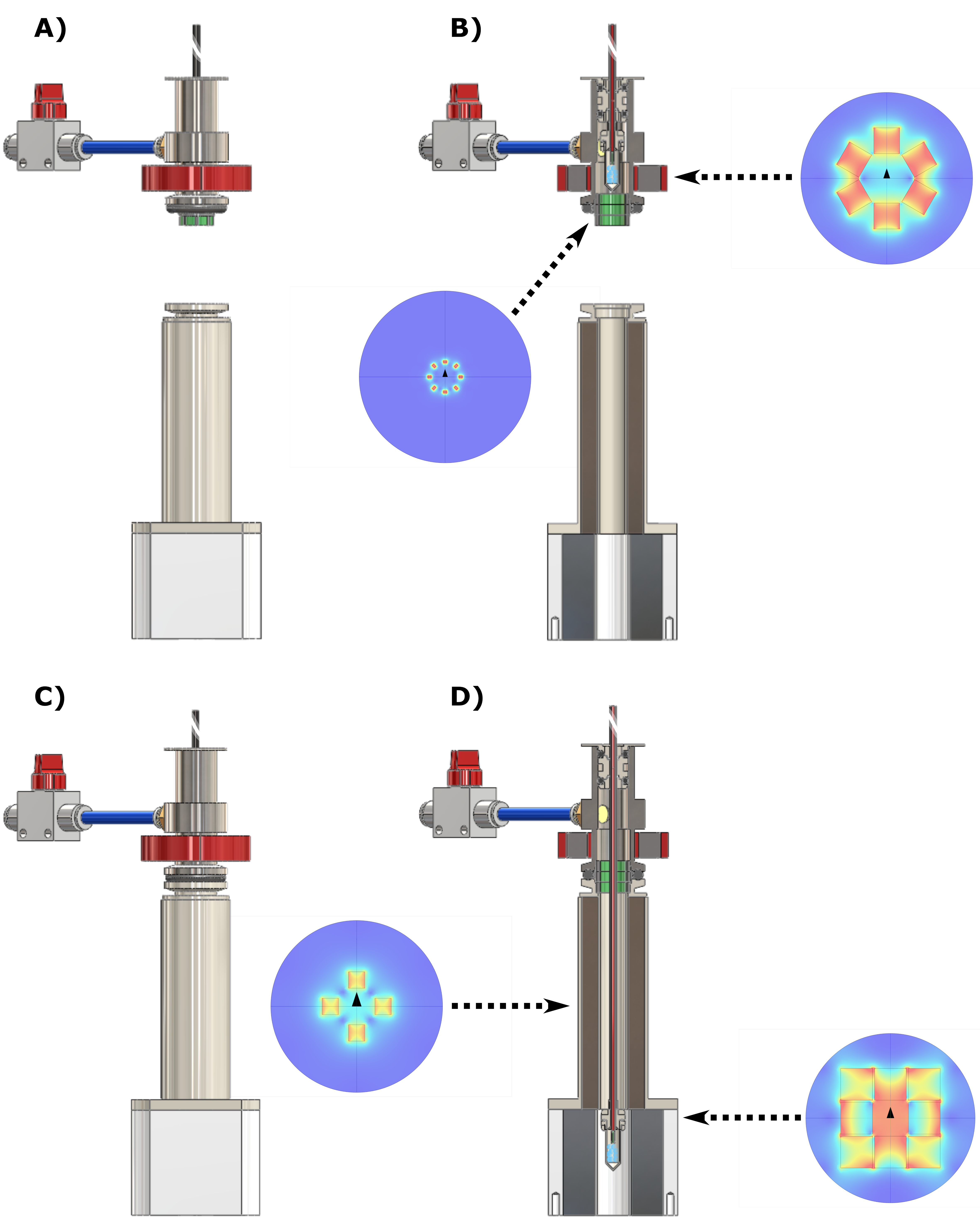
In Figure 2 we report drawings of the purpose made DNP probe we used for sample extraction. The main novelty was the insertion of permanent magnets generating a field perpendicular to the polarizer B0 to compensate the quickly decreasing vertical field for increasing distance from the isocenter.
Liquid-state 13C NMR acquisition after dissolution was performed in a 9.4 T Varian vertical high-resolution spectrometer.
Results and Discussion
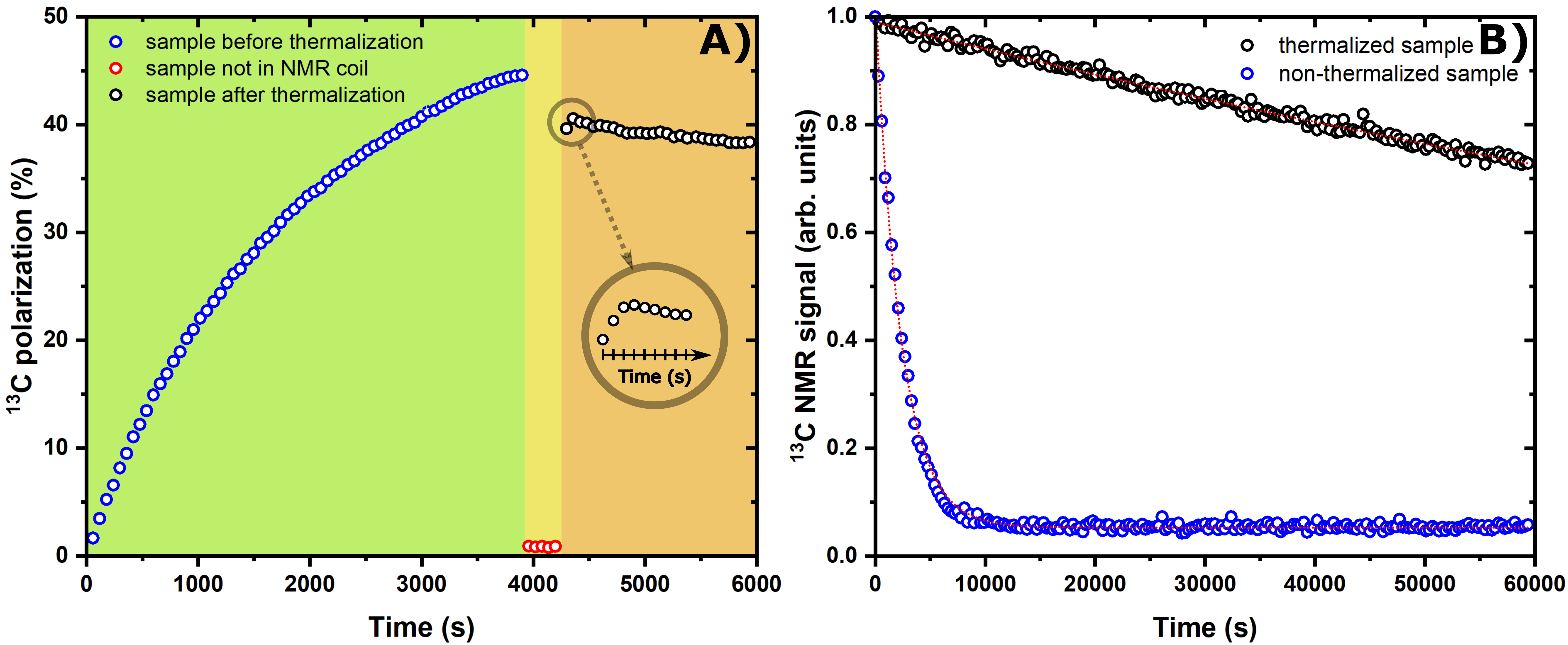
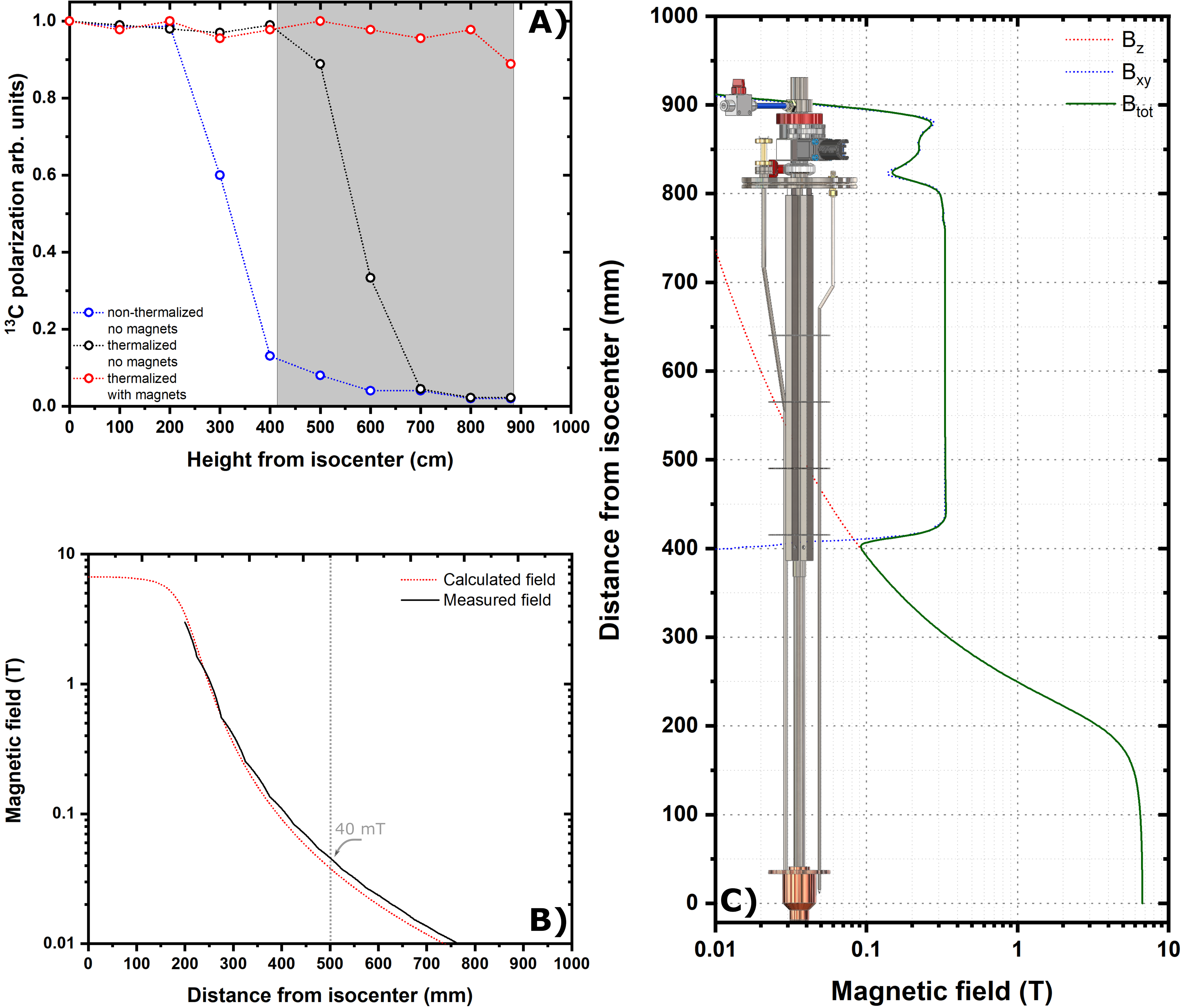
Figure 3A reports the time-course of a successful UV-radical scavenging experiment. The initial radical concentration of 40±2 mM allowed to reach a 13C polarization of 45±5% after 1 h, upon microwave irradiation (green panel). Once the plateau was achieved, microwaves were switched OFF and the sample was lifted outside the liquid He bath; He gas was blown on the sample for 20 s at 6 bar (yellow panel). The sample was then quickly re-inserted inside the NMR coil to evaluate polarization losses and verify the actual scavenging upon a second round of microwave irradiation (orange panel). At optimal conditions polarization losses were as small as 20% of the initial value. The immediate consequence of radical scavenging was the dramatic increase in glucose T1 from 0.75 h to 55 h (measured at 4.2 K and 6.7 T, see Figure 3B).In Figure 4 we demonstrate that implementing permanent magnets around the DNP probe was a sine-qua-non condition for a successful extraction of a "radical-free" HP sample. In panel A, we report the fate of a thermalized (black circles) and a non-thermalized sample (blue circles) while experiencing gradually decreasing magnetic field on the z-axis in the absence of permanent magnet. For a non-thermalized sample 350 mT (30 cm from isocenter) were enough for losing most of the polarization. Differently, a thermalized sample could be exposed to a field as low as 40 mT (50 cm from isocenter). Nevertheless, only in presence of the extra magnetic field provided by the permanent magnets the thermalised sample could reach the loading chamber while keeping its spin order (red circles).
After extraction of the sample, remote dissolution was performed in a lab placed 2 stores above the polarizer location. The transport procedure (see Figure 5) took 3 min and the best polarization result was as high as 9%.
Conclusion
The technological future of HP 13C MRI is the transport of hyperpolarization. The possibility of a remote production of 13C MCAs would be much like the way clinical examinations are performed with PET using the glucose analog 18FDGAcknowledgements
This work was supported by the Danish National Research Foundation (DNRF124); the European Union's Horizon 2020 research and innovation programme under the Marie Sklodowska-Curie grant agreement no. 713683 (COFUNDfellowsDTU); and the Swiss National Fund under the SPARK grant agreement no. CRSK-2_190547 and Ambizione grant agreement no. PZ00P2_193276.References
[1] Ardenkjaer-Larsen JH, Fridlund B, Gram A, Hansson G, Hansson L, Lerche MH, Servin R, Thaning M, Golman K (Sep 2) Increase in signal-to-noise ratio of > 10,000 times in liquid-state NMR. Proceedings of the National Academy of Sciences of the United States of America 100:10158–10163.
[2] Kurhanewicz J, Vigneron DB, Ardenkjaer-Larsen JH, Bankson JA, Brindle K, Cunningham CH, Gallagher FA, Keshari KR, Kjaer A, Laustsen C, Mankoff DA, Merritt ME, Nelson SJ, Pauly JM, Lee P, Ronen S, Tyler DJ, Rajan SS, Spielman DM, Wald L, Zhang X, Malloy CR, Rizi R (2019) Hyperpolarized (13)C MRI: Path to Clinical Translation in Oncology. Neoplasia 21:1–16.
[3] Peat DT, Hirsch ML, Gadian DG, Horsewill AJ, Owers-Bradley JR, Kempf JG (2016) Low-field thermal mixing in [1- 13 C] pyruvic acid for brute-force hyperpolarization. Phys Chem Chem Phys 18:19173–19182.
[4] Ardenkaer-Larsen JH, Axelsson OHE, Golman KK, Wolber J, Howard M (2006) Methods and devices for hyperpolarising and melting NMR samples in a cryostat. U.S. Patent and Trademark Office. Electronic Official Gazette. Patents.
[5] Abragam A, Goldman M (1978) Principles of Dynamic Nuclear-Polarization. Reports on Progress in Physics 41:395–467.
[6] Capozzi A, Cheng T, Boero G, Roussel C, Comment A (2017) Thermal annihilation of photo-induced radicals following dynamic nuclear polarization to produce transportable frozen hyperpolarized 13C-substrates. Nat Commun 8:15757.
[7] Capozzi A, Patel S, Gunnarsson CP, Marco-Rius I, Comment A, Karlsson M, Lerche MH, Ouari O, Ardenkjaer-Larsen JH (2019) Efficient Hyperpolarization of U-(13) C-Glucose Using Narrow-Line UV-Generated Labile Free Radicals. Angewandte Chemie 58:1334–1339
[8] Malinowski RM, Lipso KW, Lerche MH, Ardenkaer-Larsen JH (2016) Dissolution Dynamic Nuclear Polarization capability study with fluid path. J Magn Reson 272:141–146.
[9] Lipso KW, Bowen S, Rybalko O, Ardenkjaer-Larsen JH (2017) Large dose hyperpolarized water with dissolution-DNP at high magnetic field. Journal of magnetic resonance 274:65–72.
Figures