3542
Directional effect of frequency-encoding gradient on T2WI-STIR imaging: a phantom study to evaluate the metal artifact1Radiology, Jiangsu Province Hospital, Nanjing, China, 2GE Healthcare, MR Enhanced Application China, Beijing, China, 3GE Healthcare, MR Research China, Beijing, China
Synopsis
This study aimed to determine the optimal direction of the frequency-encoding gradient when acquiring T2WI-STIR images with titanium alloy. To investigate this, we made in vitro MRI experiment. The water-pork phantom with ten different-length titanium alloys was constructed, and the short- and long-axis ratios calculated in different frequency-encoding directions were compared with each other, respectively. We found that when the frequency-encoding axis was perpendicular to the screw, the metallic artifact was smaller in whatever long axis or short axis. This result may improve observing more anatomical structures around the embedded metal.
Introduction
Magnetic resonance imaging (MRI) for high soft-tissue contrast has been applied in the musculoskeletal (MSK) system. However, it remains challenging to acquire T2WI fat-suppressed images for MSK tissues with metal implanted for clinical purposes, largely due to strong magnetic field inhomogeneity. So far, few studies have focused on the metal-reduced artifact of T2WI fat-suppressed imaging, which is often applied in MSK imaging, although this artifact on T1WI was investigated previously.1 On the other hand, the directional frequency-encoding gradient was strongly related to the metal artifact, and the choice of the direction of the frequency-encoding gradient depended on the area of clinical interest. We have previously shown that the STIR technique effectively reduces metal artifact,2 so it is interesting to find the relationship between T2WI-STIR imaging and the directional frequency-encoding gradient. Therefore, the main goal of this study was to investigate if T2WI with STIR incorporated can achieve minimal metal artifact in a phantom with metal embedded by optimizing the frequency-encoding gradient direction.Materials and methods
A phantom was self-made using ten different-length titanium alloy pedicle screws suspended in the water-pork phantom center. All sagittal MR images were obtained parallel to the long axis of the screw, using STIR technique. In T2WI-STIR images, according to the American Society for Testing and Materials (ASTM) F2119-01,3 the apparent long- and short-axis lengths of the screw were measured when the frequency-encoding gradient was parallel or perpendicular to the long axis. The long- and short-axis ratios were defined as (measured length) / (actual length). Imaging parameters were TR 3029 ms, TE(eff) 85 ms, ETL 15, matrix 256×192, FOV 256×256, BW 83.34 kHz, and slice thickness 3 mm. Total scan time was 2 minutes, 56 seconds. The obtained long- and short-axis ratios were compared when the frequency-encoding gradient was parallel to the long-axis or perpendicular to the long axis. Additionally, the long-axis ratios and short-axis ratios calculated in different frequency-encoding directions were also compared with each other, respectively. All statistical analyses were performed using the Wilcoxon signed-rank test. The significance threshold was set as P < 0.05.Results
In phantom measurement, the short-axis length was approximately three times greater than the actual screw length, while the long-axis length was similar to the true measurements (table 1). When the direction of the frequency-encoding gradient was parallel to the long axis of the screw, both short-axis and long-axis ratios were smaller compared with those at the frequency-encoding perpendicular to the screw (P < 0.05) ( table 1).Discussion
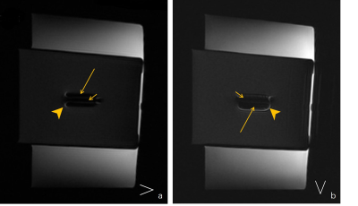
In this phantom study, when the frequency-encoding gradient was applied parallel with the long-axis screw, less metal artifact was displayed in whatever long-axis or short-axis direction than setting the frequency-encoding gradient perpendicular to the long-axis screw.The region around the metal implanted was usually a specific area of interest in clinical diagnosing. However, the metal artifact often limits the observation of anatomy. Since our previous study demonstrated that the STIR technique showed the least metal artifact compared to FSFS and IDEAL,2 STIR imaging was utilized in this experiment. In the T2WI-STIR images, metal artifacts were composed of inhomogeneous signals, including low and high signal intensities (Fig.1(a-b)). The lower signal outside the screw was originated from fat. It can be explained that the field perturbations caused faster transverse relaxation, thus led the fat signal to almost zero. The high signal around the screw was probably the unsaturated fat from in-plane or through-plane. This phenomenon can be explained that the titanium alloy was a paramagnetic material,so that it may shorten the T1 value of fat, resulting in a change of the null point in STIR.
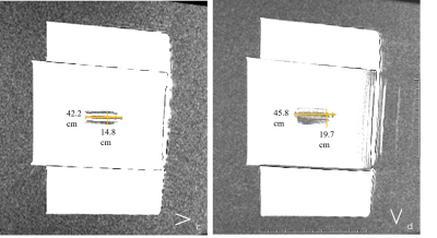
Additionally, the short- and long-ratios revealed that the artifact length was longer in the phase-encoded direction(Fig.1(c-d)). One reason may be that the orientation of the screw in the phantom was perpendicular to the static magnetic field leading to the particular field perturbations;4 another reason may be that the screw shape has a larger interface with pork oil in phase-encoded direction, resulting in changed local magnetic fields, further reducing the effectiveness of fat suppression. Furthermore, longer artifact length in the short axis was produced when the frequency-encoding gradient was applied perpendicular to the long-axis screw. The reason was that susceptibility artifacts were more extended in the frequency direction. However, it was not clear why the longer artifact length in the long axis. This finding was slightly different from Frazzini’s results,5 which showed the shorter artifact in the long axis.
Acknowledgements
We thank Synthes GmbH company (Switzerland) for generously providing the screw used in this study.References
1. Lewin JS, Duerk JL, Jain VR, et al. Needle localization in MR-guided biopsy and aspiration: effects of field strength, sequence design, and magnetic field orientation. AJR Am J Roentgenol. 1996;166(6):1337-1345.
2. Lulu X, Liang Q, Weiqiang D, et al. The evaluation of the metal artifact and SNR changes in multiple fat-suppression techniques:a phantom study. ISMRM, 2019.
3. ASTM. Standard test method for evaluation of MR image artifacts from passive implants. 2001.
4. Schenck JF. The role of magnetic susceptibility in magnetic resonance imaging: MRI magnetic compatibility of the first and second kinds. Med Phys. 1996;23(6):815-850.
5. Petersilge CA, Lewin JS, Duerk JL, et al. Optimizing imaging parameters for MR evaluation of the spine with titanium pedicle screws. AJR Am J Roentgenol. 1996;166(5):1213-1218.
Figures


