3534
Dispersing FID artifact uniformly by modulating phase of 180 degrees pulse of Spin Echo sequence with quadratic function.1Healthcare Business Unit, Hitachi, Ltd., Kashiwa, Japan
Synopsis
T1 weighted image is acquired using Spin Echo sequence in almost clinical routine practices. FID signal induced by 180 degrees pulse causes zipper artifact at the center of the image. To move the artifact to the edge of the image, the phase of RF pulse is controlled as 0 and 180 degrees alternately. However, higher parallel imaging factor cannot be applied due to the FID artifact still exist at the edge of FOV. In this study, FID artifact was dispersed uniformly by modulating phase of 180 degrees pulse with quadratic function, and higher parallel imaging factor was applied in vivo.
Purpose
The purpose of this study is dispersing FID artifact uniformly in T1 weighted image (T1WI) acquired with Spin Echo (SE) sequence and apply higher parallel imaging factor.Introduction
T1WI is acquired in clinical routine practices by using SE sequence with short TR and short TE. In T1WI, FID signal induced by the 180 degrees pulse causes zipper artifact in the center of the image [1]. To move the artifact to the edge of the FOV, phase of RF pulse is controlled as 0 and 180 degrees alternately. However, the artifact still exists at the edge of the FOV, the use of parallel imaging is limited to small acceleration factor. Recently, we proposed algorithm of decomposing FID artifact from T1WI [2]. The method uses information of phase distribution measured from center of k-space data. So the accuracy of decomposition depends on the accuracy of phase estimation. In this study, the FID artifact was dispersed uniformly by modulating RF phase of 180 degrees pulse, and signal intensity of FID artifact was suppressed as $$$1/\sqrt{N}$$$ . And higher parallel imaging acceleration factor was applied in vivo.Materials and Methods
Modulation of RF phase of 180 degrees pulseWe propose modulation of RF phase of 180 degrees pulse as equation 1.
$$θ_k=\frac{\pi}{N}k^2 \hspace{10pt} (1)$$
Where k is phase encode number, and N is total number of phase encoding: N=#ph/R. Then FID signal in k-space is modeled as equation 2. The amplitude of FID signal is constant along phase encode direction, the amplitude is assumed as 1 in equation 2.
$$S(k)=\exp(iθ_k ) \hspace{10pt} (2)$$
FID artifact in image domain is FFT of FID signal, signal intensity of FID artifact is described as equation 3, and magnitude of signal intensity of FID artifact is described as equation 4.
$$\begin{eqnarray}I(x)&=&\frac{1}{\sqrt{N}}\sum_{k=0}^{N-1}\exp\left(iθ_k\right)\exp\left(\frac{2\pi i kx}{N}\right) \\&=& \frac{1}{\sqrt{N}}\sum_{k=0}^{N-1}\exp\left(\frac{i\pi\left(k^2+2kx\right)}{N}\right) \\&=&\frac{1}{\sqrt{N}}\sum_{k=0}^{N-1}\exp\left(\frac{i\pi\left(\left(k+x\right)^2-x^2\right)}{N}\right) \hspace{10pt}(3)\end{eqnarray}$$
$$\begin{eqnarray}\mid I(x)\mid^2 &=&\frac{1}{N}\left[\sum_{k=0}^{N-1}\exp\left(\frac{i\pi\left(\left(k+x\right)^2-x^2\right)}{N}\right)\right]\left[\sum_{k=0}^{N-1}\exp\left(\frac{-i\pi\left(\left(k+x\right)^2-x^2\right)}{N}\right)\right]\\&=&\frac{1}{N}\left[\sum_{k=0}^{N-1}\exp\left(\frac{i\pi\left(\left(k+x\right)^2\right)}{N}\right)\right]\left[\sum_{k=0}^{N-1}\exp\left(\frac{-i\pi\left(\left(k+x\right)^2\right)}{N}\right)\right]\\&=&\frac{1}{N}\left[\sum_{k=1}^{N-1}\left\{\exp\left(\frac{i\pi\left(\left(k+x\right)^2\right)}{N}\right)+\exp\left(\frac{i\pi x^2}{N}\right)\right\}\right]\left[\sum_{k=1}^{N-1}\left\{\exp\left(\frac{-i\pi\left(\left(k+x\right)^2\right)}{N}\right)+\exp\left(\frac{-i\pi x^2}{N}\right)\right\}\right] \hspace{10pt} (4)\end{eqnarray}$$
Magnitude of signal intensity at the next pixel is described as equation 5.
$$\begin{eqnarray}\mid I(x+1)\mid^2 &=&\frac{1}{N}\left[\sum_{k=0}^{N-1}\exp\left(\frac{i\pi\left(\left(k+x+1\right)^2-\left(x+1\right)^2\right)}{N}\right)\right]\left[\sum_{k=0}^{N-1}\exp\left(\frac{-i\pi\left(\left(k+x+1\right)^2-\left(x+1\right)^2\right)}{N}\right)\right]\\&=&\frac{1}{N}\left[\sum_{k=0}^{N-1}\exp\left(\frac{i\pi\left(\left(k+x+1\right)^2\right)}{N}\right)\right]\left[\sum_{k=0}^{N-1}\exp\left(\frac{-i\pi\left(\left(k+x+1\right)^2\right)}{N}\right)\right]\\&=&\frac{1}{N}\left[\sum_{k=1}^{N}\exp\left(\frac{i\pi\left(k+x\right)^2}{N}\right)\right]\left[\sum_{k=1}^{N}\exp\left(\frac{-i\pi\left(k+x\right)^2}{N}\right)\right]\\&=&\frac{1}{N}\left[\sum_{k=1}^{N-1}\left\{\exp\left(\frac{i\pi\left(k+x\right)^2}{N}\right)+\exp\left(\frac{i\pi\left(N+x\right)^2}{N}\right)\right\}\right]\left[\sum_{k=1}^{N-1}\left\{\exp\left(\frac{-i\pi\left(k+x\right)^2}{N}\right)+\exp\left(\frac{-i\pi\left(N+x\right)^2}{N}\right)\right\}\right] \hspace{10pt} (5)\end{eqnarray}$$
When N is even, equation 6 holds.
$$\begin{eqnarray}\exp\left(\frac{i\pi\left(N+x\right)^2}{N}\right)&=&\exp\left(\frac{i\pi\left(N^2+2Nx+x^2\right)}{N}\right)\\&=&\exp\left(\frac{i\pi x^2}{N}\right) \hspace{10pt} (6)\end{eqnarray}$$
So $$$\mid I(x)\mid^2=\mid I(x+1)\mid^2$$$ holds, and signal intensity is constant along phase encoding direction. FID artifact was dispersed uniformly by modulating RF phase of 180 degrees pulse as equation 1.
Numerical calculation
Numerical calculation was conducted to confirm signal distribution and signal intensity of FID artifact. Number of phase encoding was set 128, 192, 256, and 512.
Experiments
Experiment was conducted on a 3 Tesla whole body MRI system (Hitachi, Ltd.). A phantom and a healthy volunteer were evaluated. This study was approved by the ethics committee of Hitachi group headquarters. 32 channels receive coil was used. Because T2 of phantom is shorter than volunteer, to confirm FID artifact clearly, crusher pulse was not applied on phantom experiment. Scan parameters of T1WI were as follows; TR / TE = 500 / 11 ms, thickness = 5 mm, FOV = 230 mm, Freq# x Phase# = 256 x 256, and scan time was 2 min 10 sec. In this study, parallel imaging factor of 2 was applied.
Evaluation
SNR was evaluated on phantom study. And line profile along the FID artifact was evaluated on phantom and volunteer study.
Results and discussions
Figure 1 shows proposed phase modulation of 180 degrees pulse described as equation 1 and corresponding signal intensity of FID artifact. The phase is expressed modulo 360 degrees. Signal intensity of FID artifact was constant. Magnitude of FID artifact calculated by equation 3 is showed in Table 1. As number of phase encode increases, magnitude of FID artifact is suppressed to $$$1/\sqrt{N}$$$. Figure 2 shows phantom image. By modulating phase as equation 1, FID artifact dispersed along phase encoding direction as confirmed on red arrow. In Figure 2 (c), the zig-zag behavior of signal intensity due to the FID artifact on conventional image was improved by modulating phase with quadratic function. In table 2, SNR is summarized. SNR was almost same between conventional image and proposed image. Thought proposed method disperses FID artifact in entire image, magnitude of FID artifact is suppressed to $$$1/\sqrt{N}$$$, degradation of SNR was little. Figure 3 shows a volunteer image. By modulating phase of 180 degrees pulse, FID artifact was not confirmed on Figure 3 (b). And in Figure 3 (c), FID artifact was confirmed on the line of white arrow where FID artifact was confirmed on Figure 3 (a). Figure 3 (d) is line profile at the line of FID artifact. Same as phantom case, the zig-zag behavior of signal intensity was improved.Conclusions
In this study, simple method of modulation of 180 degrees pulse to disperse FID artifact uniformly was proposed. The distribution of signal intensity of FID artifact was calculated theoretically, and the magnitude was numerically calculated as a function of phase encode number. The signal intensity of FID artifact was suppressed to $$$1/\sqrt{N}$$$ compared to conventional phase control. FID artifact was not confirmed on volunteer image, where the artifact was confirmed on conventional phase controlled image. The proposed method of phase modulation enables applying higher acceleration factor for acquisition of T1WI with SE sequence in clinical routine practices.Acknowledgements
References
[1] Hoff, Michael & Andre, Jalal & Stewart, Brent. (2016). Artifacts in Magnetic Resonance Imaging. 10.1201/b19609-10.
[2] K. Ito et al. JSMRM 2020 O-053
Figures
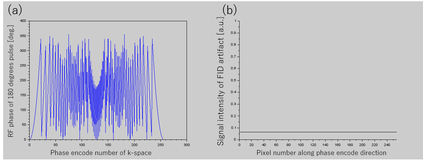
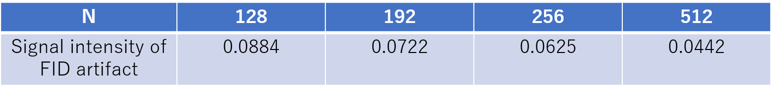
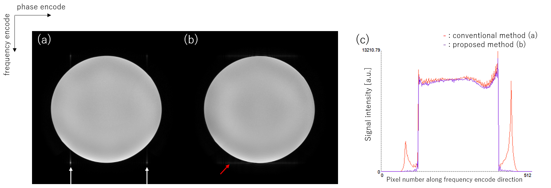
Figure 2 Phantom image
(a): conventional phase control, FID artifact is at white arrow
(b): proposed phase modulation, FID artifact is at red arrow
(c): line profile on FID artifact (left white arrow on (a))

Table 2 SNR of phantom image.
128 pixels diameter circle ROI was set at center of phantom.
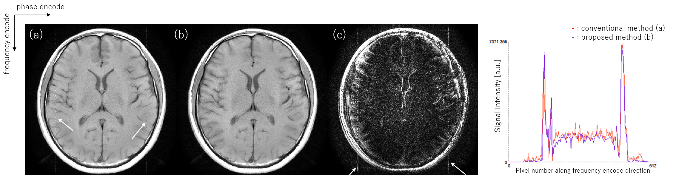
Figure 3 Volunteer T1 weighted image
(a): conventional phase control
(b): proposed phase modulation
(c): difference between (a) and (b), Window width is 1/5 of (a) and (b)
(d): line profile on FID artifact