3472
Design and Construction of an Interchangeable RF Coil System for Rodent Spinal Cord MR Imaging1Vanderbilt University Institute of Imaging Science, Vanderbilt University Medical Center, Nashville, TN, United States, 2Department of Radiology and Radiological Sciences, Vanderbilt University Medical Center, Nashville, TN, United States, 3College of nuclear equipment and nuclear engineering, Yantai University, Yantai, China, 4Department of Biomedical Engineering, Vanderbilt University, Nashville, TN, United States
Synopsis
Multiparametric MRI at high field provides comprehensive information to assess structural and functional changes that are important for clinical diagnosis and for evaluating therapies. Injuries may occur at different levels of the lumbar and thoracic cord, and the number of segments injured and their depths may vary along the spine, so it is challenging to build one universal RF coil that exhibits high-performance for all spinal cord imaging applications. We therefore developed an interchangeable RF coil system for a 9.4T small animal MRI scanner, and found the specialized coil has 2.4-fold SNR improvement compared to a commercial general-purpose sized coil.
Purpose:
Calibrated contusion injuries to the lumbar and/or thoracic spinal cords of rodents provide a model for studying neuron-intrinsic regenerative responses[1-3]. Multiparametric MRI at high field provides comprehensive information to assess structural and functional changes that are important for clinical diagnosis and for evaluating therapies. Injuries may occur at different levels of the lumbar and thoracic cord, and the number of segments injured and their depths may vary along the spine, so it is challenging to build one universal RF coil that exhibits high-performance for all spinal cord imaging applications. We therefore developed an interchangeable RF coil system for a 9.4T small animal MRI scanner, in which the users can select an optimal coil specialized for their demands.Methods:
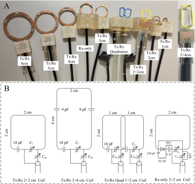
1. RF coilsFigure 1A shows the fabricated RF coils with different sizes and different drive methods (single loop T/R, quadrature T/R and single loop Rx-only). Figure 1B shows examples of circuit diagrams for a 2×2 cm Tx/Rx coil, a 2×4 cm Tx/Rx coil, 1×2 cm quadrature coils, and a 2×2 cm Rx-only coil. More distributed fixed capacitors were employed as the coil dimension increases, to adjust the value of the circuit capacitance and avoid the antenna effect. Note that the 1×2 cm quadrature coil was optimized to maximize the SNR for a special study focusing on lumbar L1-L2 level. This specialized coil was optimized following the procedure described in previous work [4].
Drive coaxial cables were carefully arranged along the virtual ground plane and no balun/trap circuits were needed for most single loop coils. For the quadrature coil with two loops, additional cable traps were employed to reduce the residual crosstalk from common-mode currents. In each coil, trimmer capacitors (Ct and Cm) were positioned along the z- direction. They were attached to 1-meter-long home-built tuning rods for remote adjustments. Coil conductors, feeding board and tuning rods, and coaxial cables were attached to a universal-sized housing, making all RF coils interchangeable. All the coils were tuned to 400.65 MHz and matched to 50 Ω and used with a 9.4T 21 cm bore animal scanner manufactured by Agilent/Magnex/Varian Inc.
2. Coil management device and animal management device
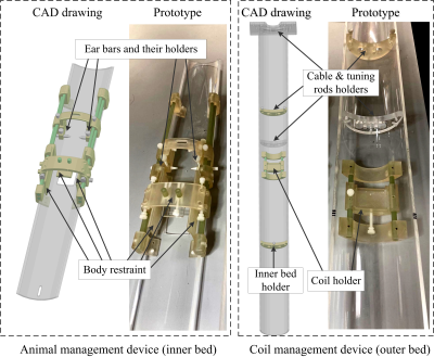
Figure 2 shows the CAD drawing and prototype of the coil and animal management devices with functionality for whole system fixation, animal immobilization, animal positioning, and RF coil exchange. The assembly was made using a ProJet 3D printer (HD 3500 Plus, 3D Systems, USA).
The whole system was attached to the front of the bore with thumbscrews to avoid possible vibration during scans. The animal positioning and immobilization system includes ear bars (and their holders) and body restraint. They are both adjustable along x-, y- z-directions for restricting different-sized animals and initial body centralization. The bed (inner tube) is separated from the coil (attached to the outer tube) so the animal can be positioned without moving the coil.
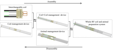
The coil management system includes supporting rings that hold the cable and tuning rods, and coil holders that lock and unlock the RF coil with thumbscrews. The holder is slidable along the z- direction to make sure that coils can always sit at the center of the bore. The coil holder allows for straightforward removal and exchange of multiple RF coils for specific applications. Figure 3 depicts the procedures of the RF coil exchange.
Results and Discussions:
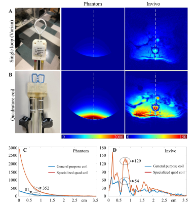
The interchangeable coil design ensures the use of an optimal RF coil that can maximize the SNR for each animal and experiment. The coil exchange can be performed rapidly before animal preparation and with the animal positioning system, the average animal preparation time can be highly reduced.For rat lumbar imaging where the region of interest is located approximately 0.8-cm-deep from the surface, we found the specialized coil (dimension 1×2 cm, quadrature drive) has significant SNR improvement compared to a commercial general-purpose coil (2 cm circular single loop coil, Varian Inc.). Compared to the general-purpose coil, the specialized coil has an SNR improvement of 4.3-fold (352 vs. 81) in a phantom (0.8-cm-deep region) and 2.4-fold (129 vs. 54) in a live rat at level L2, as shown in Figure 4.
Conclusion:
We developed an interchangeable RF coil system for a 9.4T small animal MRI scanner, allowing for optimal coil selection for different experiments. Compared to a general-purpose commercial coil, up to 2.4-fold SNR improvement was obtained by using an optimal coil specialized for rat L1-L2 spinal cord imaging.Acknowledgements
No acknowledgement found.References
1. Xu, B., Park, D., Ohtake, Y., Li, H., Hayat, U., Liu, J., Selzer, M.E., Longo, F.M. and Li, S., 2015. Role of CSPG receptor LAR phosphatase in restricting axon regeneration after CNS injury. Neurobiology of disease, 73, pp.36-48.
2. Wu, T.L., et al., Longitudinal assessment of recovery after spinal cord injury with behavioral measures and diffusion, quantitative magnetization transfer and functional magnetic resonance imaging. NMR Biomed, 2020. 33(4): p. e4216.
3. Alizadeh, A., Dyck, S. M., & Karimi-Abdolrezaee, S. (2019). Traumatic spinal cord injury: an overview of pathophysiology, models and acute injury mechanisms. Frontiers in neurology, 10, 282.Chicago
4. Lu, M., et al., Optimization of a transmit/receive surface coil for squirrel monkey spinal cord imaging. Magn Reson Imaging, 2020. 68: p. 197-202.
Figures


