3361
A Simple Device for Real-Time Detection of Head and Body Movements in a Mock Scanner, for Screening and Training Subjects
Fadi Ayad1 and Amir Shmuel2
1Biomedical Engineering, McGill University, Montreal, QC, Canada, 2McConnell Brain Imaging Centre, Montreal Neurological Institute, Montreal, QC, Canada
1Biomedical Engineering, McGill University, Montreal, QC, Canada, 2McConnell Brain Imaging Centre, Montreal Neurological Institute, Montreal, QC, Canada
Synopsis
Head and body movements introduce artifacts in structural, diffusion, and functional MRI. With the advent of imaging at ultra-high field, head and body movements limit our capacity to obtain high-resolution, high-quality data. We have developed a small wearable device for acquiring data on head and body movements and transmitting it wirelessly to a computer for real-time analysis while a subject is trained in a mock MRI scanner. This device works in parallel to an in-bore camera used for movement detection, to support subject screening and training to remain still in preparation for MRI.
Introduction
The most important characteristic of a 'good' subject for MRI and fMRI is the ability to stay still during the imaging session. The primary reason is straightforward: if the subject's head moves, the structural images will be blurred or sheared, and the functional images will show spurious activations or spurious functional connectivity. Movements in the MRI environments introduce additional problems. For example, if the subject moves his head or body during a scan, the shimming performed prior to the scan is not correct anymore, because the subject’s movement changes the magnetic field (Pfeuffer et al., 2007). This causes distortions and unreliable detection of activation. Therefore, it is essential to prevent subjects' head and body movements during MRI and fMRI.Head and body movements introduce artifacts in structural, diffusion, and functional MRI. With the advent of imaging at ultra-high field, head and body movements are one of the factors that limit our capacity to obtain high-resolution, high-quality data. We have developed a small wearable device with the purpose of acquiring data on head and body movements and transmitting it wirelessly to a computer for real-time analysis while a subject is trained in a mock MRI scanner environment. This device works in parallel to an in-bore camera used for movement detection, to support subject screening and training to remain still in preparation for MRI.
Methods
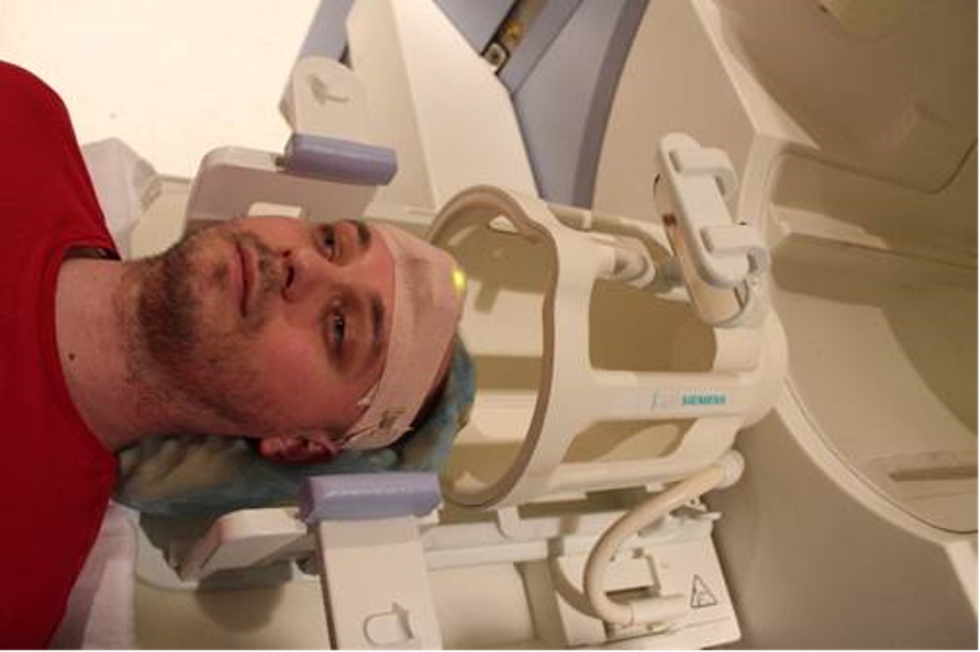
Our setup consists of a motion sensor system, an in-bore video camera, a high-volume audio system for mimicking MRI noise, and a computer (Figure 1). The motion sensor system consists of two highly sensitive, three axis sensor nodes and a receiver station that receives the signals from the sensors in a wireless mode and sends them to the computer (Figures 2-3). As shown in Figure 4, the sensor nodes can be placed on the forehead and the hip of the participating subjects by means of elastic bands, to measure head and body movement, respectively.The receiver station receives the movement information transmitted wirelessly from the two sensor nodes and relays the data to the computer via a USB connection. The computer software plots the movement data in real-time on the user's screen and can provide feedback to the subject, which can be projected onto a screen placed at the bore of the mock scanner.
The video camera (sampling frequency 30 Hz) can capture video in light and dark conditions by utilizing infra-red light. It is used for viewing the subject and for real-time analysis of movements complementing the detection by the sensors.
In addition, the software can play audio files that mimic the noise of several MRI protocols. These sound files were acquired by recording the noise from a 3T MRI scanner running several sequences using an MRI compatible microphone. The training can be pursued in parallel to training the subjects to perform a perceptual or motor task. The software analyzes the movement data in real-time and alerts the user and the subject when a movement beyond the accepted thresholds occurs.
Results
Data collected in two 10-minutes-long runs are shown in Figures 5 and 6. The first two subplots (red and orange) illustrate the movements detected by sensors 1 and 2, respectively, whereas the third and fourth subplots (black and blue) represent the movement detected by processing the video. In the third subplot (black), the movement is estimated in relation to a reference frame taken at the beginning of the entire run. In the fourth subplot (blue) the movement is estimated between each consecutive frames.Conclusions
In addition to distortions, head movements during structural MRI lead to an underestimation of grey matter volume and thickness; the underestimation is directly proportional to the level of movement (Reuter at al, 2015; Savalia et al., 2017). For fMRI, head movement is even more challenging because even sub-millimeter movements strongly affect data by introducing false correlations between voxels that are far from each other (Power et al., 2014; Satterthwaite et al., 2012).The proposed system can be used to screen and train human subjects or alert animals to stay still in the MRI. It can also be used for gradually accommodating special subject populations such as subjects with neurodevelopmental disorders. The device can contribute to improving imaging quality and reducing the cost of imaging human subjects that are prone to moving and thus producing unusable data. These costs will be reduced by screening subjects in a mock scanner prior to the actual MRI session. Given the increase in ultra-high-field (7 Tesla and higher) MRI systems around the world, the implementation of this device is even more important, since movement artifacts are accentuated and especially detrimental in high-field imaging.
As evident from Figures 5 & 6, both the sensor system and the video camera provide information about the subject movement that are not entirely similar. The two methods are sensitive to different types of movements that do not completely overlap; thus, the sensors and camera systems provide a more accurate estimation of the subject’s movements. We are currently working on a version that can function in the MRI scanner.
Video Demonstation
https://mcgill-my.sharepoint.com/:v:/g/personal/fadi_ayad_mail_mcgill_ca/EQRirnFXpsFIrIFf0sWgw0cB2UbfG-6EHHfgWs3PbjtMrg?e=fcWOWnFor attendees who are interested in receiving such a system Please send an email to amir.shmuel@mcgill.ca
Acknowledgements
This study is supported by grants from the FRQS Quebec Bioimaging Network and the Canadian Institute of Health ResearchReferences
1- Pfeuffer J, Shmuel A, Keliris G, Steudel T, Merkle H, Logothetis NK (2007) Functional MR imaging in the awake monkey: effects of motion on dynamic off-resonance and processing strategies. Magnetic Resonance Imaging, 25(6):869-882.2- Power J. D., Mitra A., Laumann T. O., Snyder A. Z., Schlaggar B. L., Petersen S. E. (2014) Methods to detect, characterize, and remove motion artifact in resting state fMRI. NeuroImage 84, 320-341.
3- Reuter M., Qureshi A., Buckner R. L., van der Kouwe A. J. W., Fischl B (2015) Head motion during MRI acquisition reduces gray matter volume and thickness estimates. NeuroImage, 107, 107-115. doi:http://dx.doi.org/10.1016/j.neuroimage.2014.12.006
4- Satterthwaite T. D., Wolf D. H., Loughead J., Ruparel K., Elliott M. A., Hakonarson H., Gur R. C. Gur R. E. (2012) Impact of in-scanner head motion on multiple measures of functional connectivity: Relevance for studies of neurodevelopment in youth. Neuroimage 60: 623-632.
5- Savalia N. K., Agres P. F., Chan M. Y., Feczko E. J., Kennedy K. M., Wig G. S. (2017) Motion-Related Artifacts in Structural Brain Images Revealed with Independent Estimates of In-Scanner Head Motion. Human Brain Mapping 38:472–492.
Figures
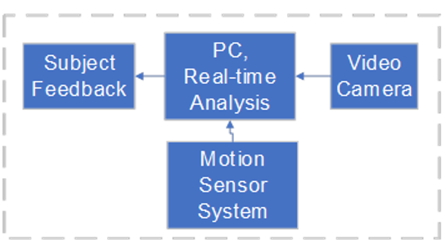
Figure
1: System Architecture
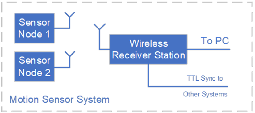
Figure
2: Motion Sensor System
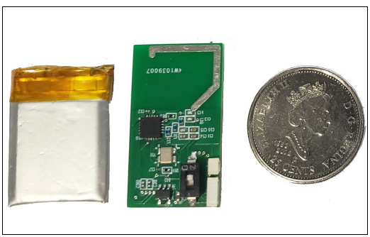
Figure 3: Sensor Node Assembly
Figure
4: The head movement sensor attached to a subject’s forehead. Note the green
LED light, indicating that the sensor is powered up by the battery. This photo
was taken while the subject was in the supine position on the patient bed of a
mock scanner.
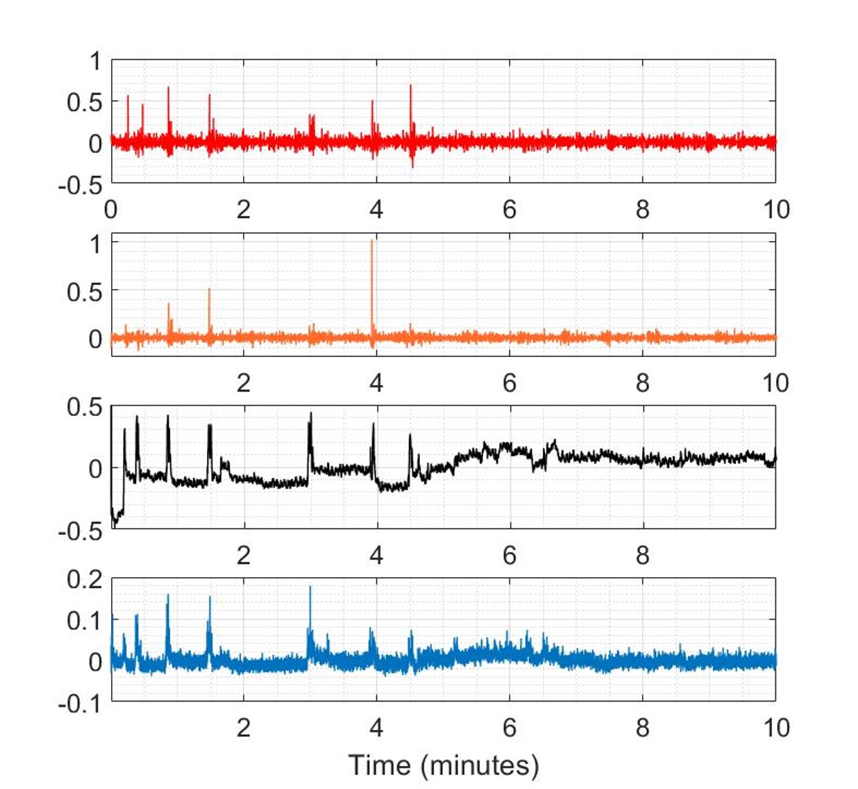
Figure
5: Sample Data from Subject 1
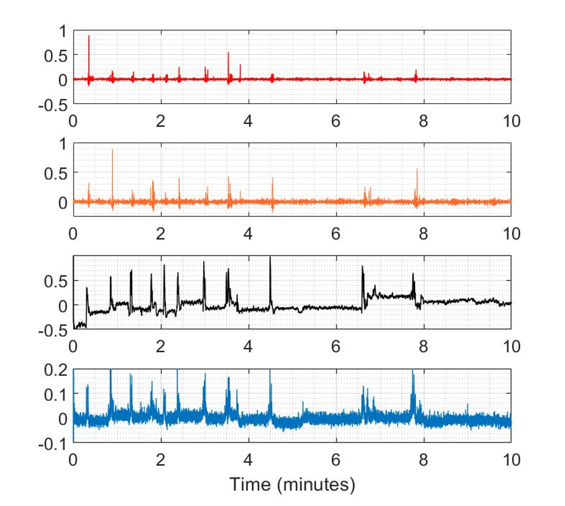
Figure
6: Sample from Subject 2