3360
OpenCV based RF field mapping for MR coil assessment1Max Delbrück Center for Molecular Medicine, Berlin, Germany, 2School of Biomedical Engineering, Southern Medical University, Guangzhou, China, 3Independent Researcher, Paris, France
Synopsis
This work presents a cost-effective near-field RF mapping approach for accurate tracking of a field probe. The method is based on the OpenCV library. It serves as a practical tool for the rapid assessment and characterization of MR coils and arrays. The only equipment required for the setup is a field probe, a regular webcam, and a paper QR code label, which renders this technique highly accessible and easy-to-use.
Introduction
Near-field RF mapping is a routine experimental technique to validate numerical electromagnetic simulations. It is of high relevance for the design and assessment of the MR coils1, RF-shields2, pTx systems3, or field interference safety tests4. The process of the field mapping is based on the movement of a measuring probe in a given 3-d or 2-d region with the help of various kinds of CNC machines5, robotic arms6, or even 3D printers7. The need for such equipment makes these methods quite expensive, especially in cases where a high precision or a large working volume coverage is required. Computer vision tracking provides a viable alternative to heavy and bulky positioning machinery and offers a cost-efficient and accessible tool for field distribution measurements. A field probe equipped with a QR code marker can be easily recognized in the image frame, even from a standard webcam. To extract the spatial position of a marker from image data the OpenCV framework offers fast algorithms for real-world coordinate calculation tasks8. Recognizing this opportunity this work examines the feasibility of OpenCV-based RF field mapping. For this purpose, we demonstrate the applicability of the method for tracking a hand-held probe or for high fidelity RF field mapping with an inexpensive robotic arm.Methods
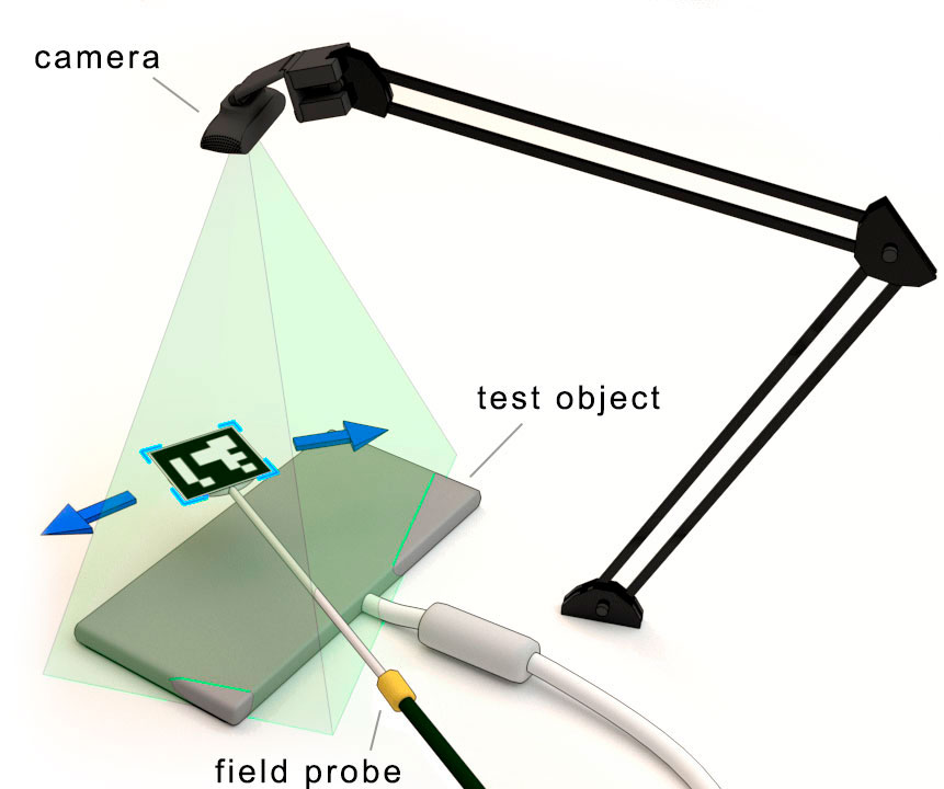
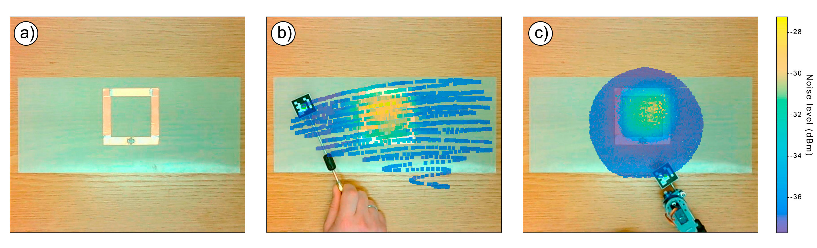
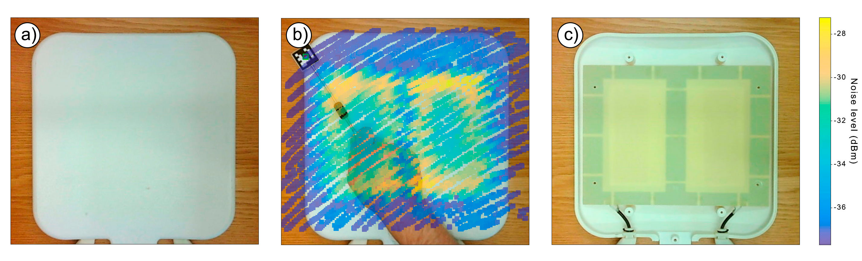
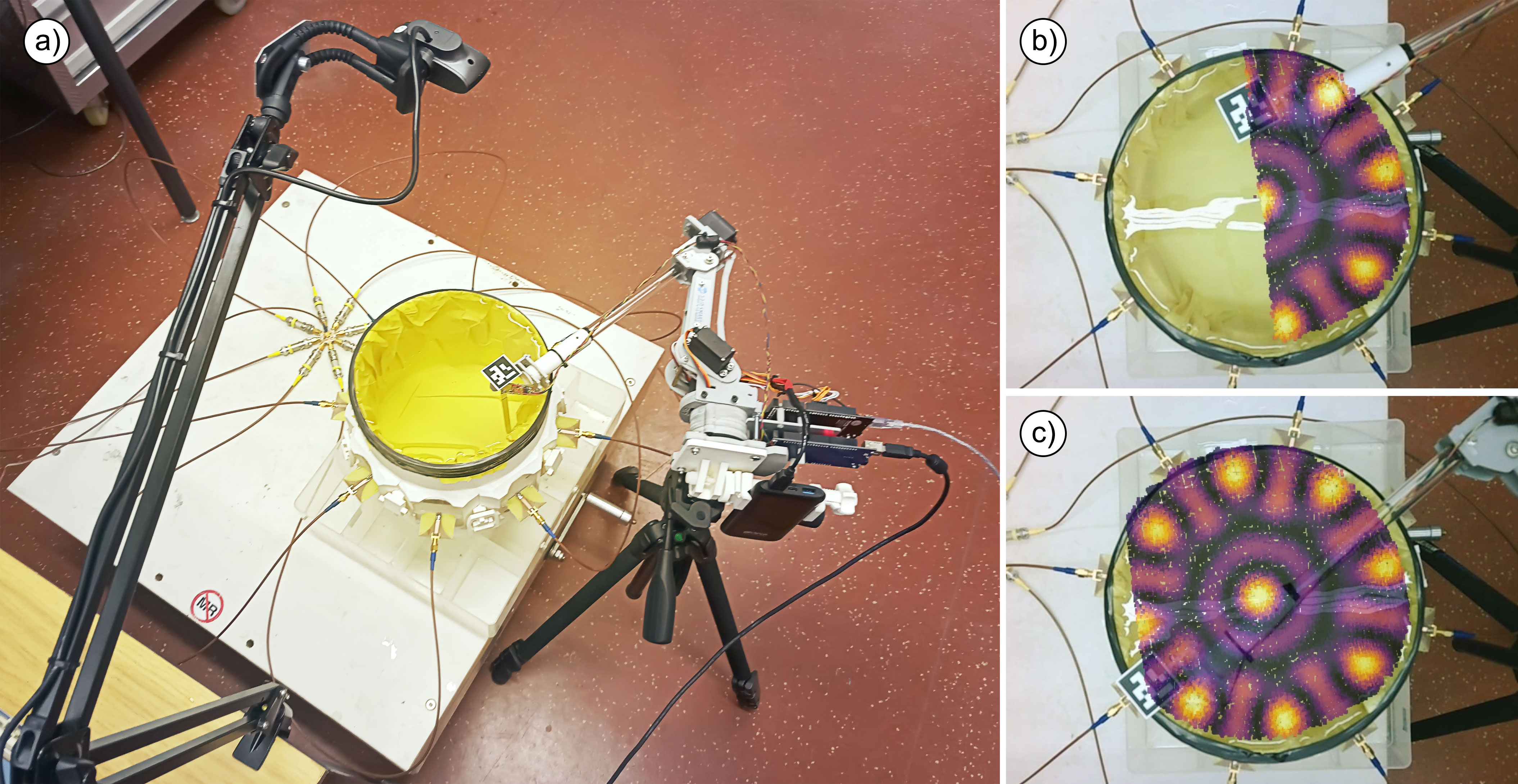
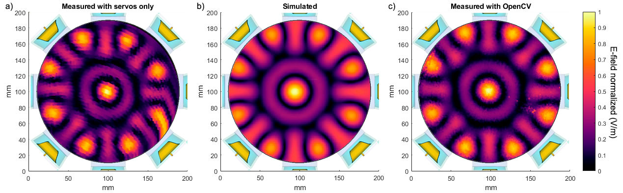
The main components of the experimental setup for the MR coil assessment are shown in Figure 1. We employed a webcam with regular characteristics (Trust Trino HD) at 640p resolution and a frame rate of 30 fps mounted on a stand. The webcam detects a QR-code with the use of the OpenCV library. The QR-code marker is attached to the symmetrical RF magnetic field probe9 allowing the webcam to track its position within the image frame. The probe is connected to software-defined radio (SDR) receiver USB dongle to measure RF level. The correlation between the noise level and the magnitude of the magnetic field makes it possible to estimate its value. For each frame received from the camera, an RMS value is calculated and displayed as a color pixel on the overlaid color map in the camera image. For experimental validation, we used a square-shaped resonant loop tuned to 114 MHz (Figure 2) as a standard test object, the anterior section of a 4-channel RF coil array10 (Figure 3) tailored for cardiac MRI at 7.0 T (f=297.5 MHz) and an array of eight self-grounded bow tie (SGBT) antenna11. The positioning of the probe was done (i) manually and (ii) by using a low-cost robotic arm with two degrees of freedom. The second experimental setup serves to map the electric field interference (Figure 4). It includes an array of SGBT antennas in a cylindrical water tank, powered with the same amplitude and phase at 700 MHz frequency. The measurements were done by replacing the magnetic field probe with a homebuilt E-field probe. The servo-based robotic arm was driven in two modes: with and without OpenCV tracking. For evaluation of the measurements, EMF simulations were performed in CST (CST Studio Suite 2018, CST – Computer Simulation Technology GmbH, Darmstadt, Germany) with the frequency-domain solver (Figure 5).Results
Field mapping of a single resonant loop element using a human hand and a robotic arm for holding the probe is shown in Figure 2. The scan plane was placed about 30 mm above the surface of the loop antenna. The measurements revealed an estimated higher RF noise level in the center of the loop since it is working as an efficient magnetic antenna at the resonant frequency. Figure 3 demonstrates a manually measured H-field distribution for the 7.0 T cardiac RF coil array. For this purpose, the field probe was placed right on top of the array's cover. Mapping the array fields revealed the geometry and the number of internal RF elements. The method feasibility for mapping E-field interferences is demonstrated in Figure 4. A closer examination highlighted in Figure 5 shows that the robotic arm alone has suboptimal mechanical stability. This shortcoming results in a distortion of the field map versus the EMF simulations. This distortion and deviation can be addressed if the RF field mapping is combined with the computer vision tracking so that the measured data matches the simulated data.Discussion and Conclusion
Our results demonstrate that OpenCV is a powerful and simple tool for tracking a variety of sources in motion, including handheld or robotically-driven field probes. Our method supports high fidelity RF field mapping that affords a rapid and convenient evaluation of MR coils, resonant circuits, and, in perspective, EMI sources detection without the need for extra and expansive positioning systems. The limitations of the current implementation are the necessity of direct visual contact between the camera and the field probe and proper lighting conditions during the measurement. Despite the camera playing an essential role in the setup, convincing results are achievable with a standard webcam. All scripts required to use the method are publicly available as open-source12.Acknowledgements
This project has received funding from the European Research Council (ERC) under the European Union's Horizon 2020 research and innovation program under grant agreement No 743077 (ThermalMR).References
1. Kozlov M, Lucano E, Angelone LM. Effects of tuning conditions on near field of MRI transmit birdcage coil at 64 MHz. Conf Proc IEEE Eng Med Biol Soc. 2016 ;2016:6242-6245.
2. Kuzmin, V., Bidinosti, C., Hayden, M., & Nacher, P. (2015). An improved shielded RF transmit coil for low-frequency NMR and MRI. Journal of Magnetic Resonance, 256(5), 70 – 76.
3.Winter, L, Silemek, B, Petzold, J, et al. Parallel transmission medical implant safety testbed: Real-time mitigation of RF induced tip heating using time-domain E-field sensors. Magn. Reson. Med.. 2020; 00: 1– 17.
4. Nordbeck P, Fidler F, Weiss I, et al. Spatial distribution of RF-induced E-fields and implant heating in MRI. Magn Reson Med. 2008;60(2):312-319.
5. T. K. Vo Dai, A. Thai, T. Phan, O. Kilic and K. Russo, "Construction of an Inexpensive Anechoic Chamber and Its Applications in Undergraduate Research" in IEEE Antennas and Propagation Magazine, vol. 60, no. 4, pp. 102-112, Aug. 2018
6. Wang, B., Sud, R., Leung, M., Yang, M., Rodriguez, J. A., Lee, R., et al. (2019). OpenEM – Electromagnetic field mapping robot for microwave and RF measurements. HardwareX, 5(5), e00062.
7. Vavoulas, A., Vaiopoulos, N., Hedström, E., Xanthis, C. G., Sandalidis, H. G., & Aletras, A. H. (2016). Using a modified 3D-printer for mapping the magnetic field of RF coils designed for fetal and neonatal imaging. Journal of Magnetic Resonance, 269(5), 146 - 151.
8. Siswantoro, J., Prabuwono, A.S., & Abdullah, A. (2013). Real World Coordinate from Image Coordinate Using Single Calibrated Camera Based on Analytic Geometry.
9. Roy Ediss. Probing the magnetic field probe. EMC & Compliance Journal, July 2003.
10. Dieringer MA, Renz W, Lindel T, Seifert F, Frauenrath T, von Knobelsdorff-Brenkenhoff F, Waiczies H, Hoffmann W, Rieger J, Pfeiffer H, Ittermann B, Schulz-Menger J, Niendorf T. Design and application of a four-channel transmit/receive surface coil for functional cardiac imaging at 7T. J Magn Reson Imaging. 2011 Mar;33(3):736-41.
11. Eigentler, T. W., Winter, L., Han, H., Oberacker, E., Kuehne, A., Waiczies, H., et al. (2020). Wideband Self-Grounded Bow-Tie Antenna for Thermal MR. NMR in Biomedicine, 33(5), e4274.
12. https://github.com/CGrassin/EM_mapper_scripts
Figures