3352
Development of an anthropomorphic torso and left ventricle phantom for flow and respiratory motion simulation1High Field MR Center, Center for Medical Physics and Biomedical Engineering, Medical University of Vienna, Vienna, Austria, 2Medical Physics, Department of Radiology, University Medical Center Freiburg, Freiburg, Germany
Synopsis
Development of motion compensation strategies is challenging, especially when involving volunteer measurements due to high demands to subject compliance and low reproducability. In this work a human shaped torso phantom, capeable of simulating respiratory motion of a left ventricle phantom including blood flow simulation is presented. A tracking algorithm is applied in postprocessing to acquired images containing simulated respiratory motion. Comparison to motion tracking data from an external sensor show good agreement proving the setup to be an environment with high reproducability and hence ideal for the purpose to develop and evaluate motion compensation strategies.
Introduction
Motion is a dominant source for artifacts in cardiovascular magnetic resonance (CMR) [1,2]. Development and evaluation of respiratory motion compensation strategies is challenging in vivo due to high demands on subject compliance and low reproducibility of breathing patterns [3,4].This work provides a solution to develop and test respiratory motion compensation strategies without the need for human subjects in an anatomically-shaped torso phantom, providing a controlled, adjustable environment with high reproducibility (simulating blood flow and breathing patterns).
Methods
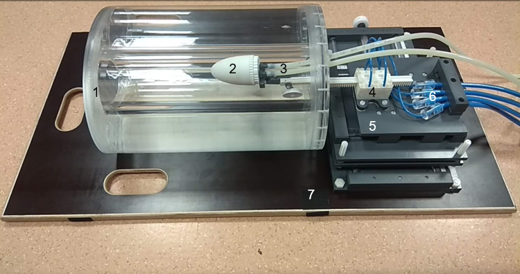
The anthropomorphic torso-shaped phantom was designed in-house and manufactured by an external contractor (Chase GmbH, Maria Enzersdorf, Austria). The lid of this phantom has two large hollow cylinders mimicking lungs, which also allows the placements of inserts.A base plate connects the torso phantom with an in-house built 3D positioning table (figure 1). To simulate respiratory motion a 3D printed pneumatic stepper motor [5] is used. Compressed air controlled by an Arduino board with associated valves, and 10 m long tubes supply the stepper motor. A 3D printed left ventricle (LV) phantom is mounted at the tip of the motor rack.
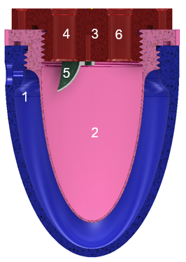
The LV phantom consists of an outer liquid filled compartment mimicking the myocardium, and an inner compartment that allows flow (figure 2). To simulate blood flow, water is flushed through the inner compartment, supplied via 10 m long tubes and a self-priming pump (Jabsco ‘water-puppy’) with a 15 l water reservoir. The flow rate is adjusted by current variations of the pump’s power supply and monitored using a flowmeter connected to the outlet of the pump. Stepper motion, flow logging and de-/activation of the pump with a relay is achieved using a Raspberry Pi 3 model B connected to the respective hardware (figure 3). A graphical user interface was programmed in “processing” [6]. It controls the pump as well as air valves outside the scanner room.
Motion tracking tests of the phantom setup were performed at a Siemens MAGNETOM 7T MR scanner (Siemens, Erlangen Germany) as described by Wampl et al. (submitted to the ISMRM 2021) [8].
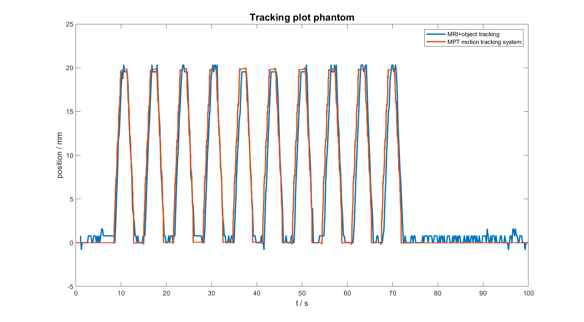
Images were acquired using a gradient echo (GRE) sequence (1 sagittal slice, FOV: 200 x 200 mm², Matrix: 265 x 265). During acquisition the stepper motor performed a linear periodic oscillating motion with 2 cm amplitude. The flow rate was set to 3 l/min. The tracking algorithm “KCF” (kernelized correlation filter) [7], as implemented in OpenCV, was applied in post processing on the acquired images to track the motion of the LV phantom. Results were compared to data recorded by the MPT motion tracking system (Metria Innovation) [9], which monitored movements of the stepper rack during acquisition.
Results
A fully MR compatible torso-shaped phantom capable of simulating motion and flow was successfully constructed and tested on a 7 T MR scanner. The stepper motor allows displacements of up to 150 mm with a precision of 1 mm and maximal speed of 10 mm/s. The pump provides flow rates ranging from 3 to 10 l/min.Comparison showed good agreement between data from the external sensor (optical tracking system) and the image-based tracking algorithm (figure 4).Discussion and Conclusion
The presented human torso-shaped phantom is capable of simulating physiological cardiac flow rates in the LV and allows the simulation of different breathing patterns.Similarity to a human torso will be increased by adding compartments into the hollow sections e.g. cylinders representing liver tissue.
A major challenge was the distance between the control room, where the external hardware ( pump and pneumatic valves) must be located and the scanner’s isocenter (8–10 m). Thus, comparably big hose diameters (¾”) are needed to maintain flow in the average range of human cardiac output (3– 10 l/min), and sufficient amounts of compressed air are required to operate the pneumatic stepper (9 bar).
Currently, runtime of the stepper motor is restricted to 4–5 min, mainly caused by the limited air supply (10 l compressed air bottles at 200 bar) and losses due to the tube length. An appropriate compressor and attempts to shorten the distance between valves and pneumatic stepper motor will permit continuous measurements in the future. The design of this setup will be extended to include more types (e.g. rotation) and directions of motion.
The presented setup works well and provides a reproducible environment for the development and quality assurance of respiratory motion compensation strategies. The mentioned improvements will extend the capabilities of the setup in the future to simulating respiratory motion of the heart as well as other organs.
Acknowledgements
This work was funded by the Austrian Science Fund (FWF) project P 28867-B30References
[1] Ehman et al (1986). Radiology, 159:3, 777-782 https://doi.org/10.1148/radiology.159.3.3704156
[2] Axel et al. (1986). Radiology, 160:3, 795-801 https://doi.org/10.1148/radiology.159.3.3704156
[3] Firmin et al. (2001). J Cardiovasc Magn Reson., 3(3),183-93 https://doi.org/10.1081/jcmr-100107467
[4] Hock et al. (2014). NMR Biomed., 27, 348-355https://doi.org/10.1002/nbm.3069
[5] Groenhuis et al. (2018). IEEE/ASME Transactions on Mechatronics. PP. 1-1. Doi: 10.1109/TMECH.2018.2840682
[6] https://processing.org/
[7] Henriques et al. (2015). IEEE TPAMI, 37(3), 583–596. https://doi.org/10.1109/TPAMI.2014.2345390
[8] Wampl et al. ISMRM 2021 Abstract #560
[9] Maclaren et al. (2012). PLOS ONE 7(11): e48088https://doi.org/10.1371/journal.pone.0048088]
Figures
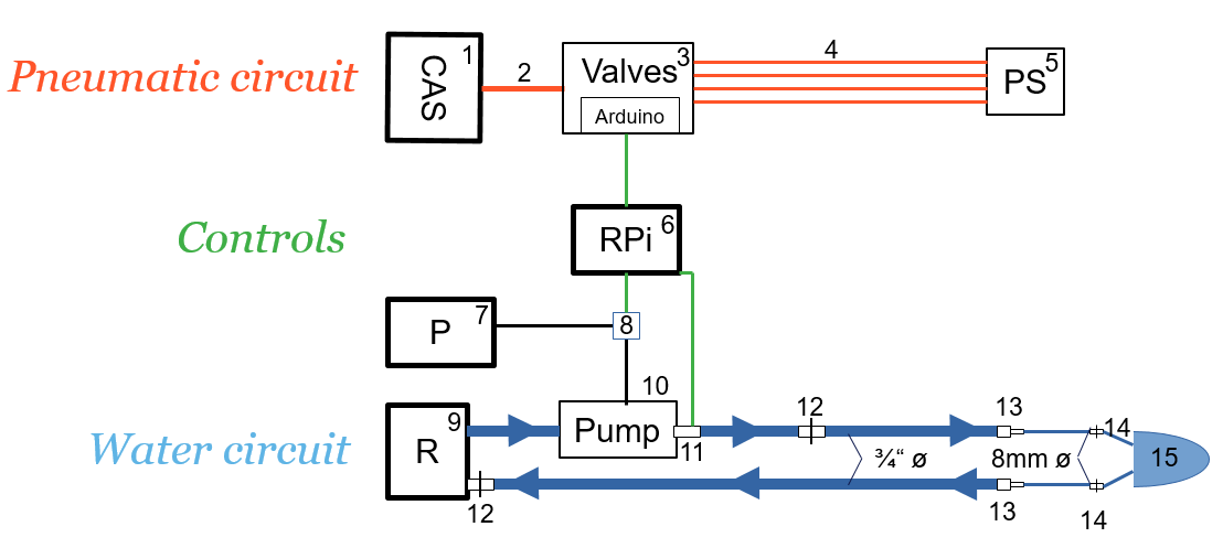
Pneumatic circuit: A compressed air supply 1 is connected 2 to air valves 3 controlled by an Arduino. The pneumatic stepper motor 5 is connected via 10 m tubes 4 to the valves.
Water circuit: A pump 10 with flow sensor 11 moves water from a reservoir 9 to a left ventricle phantom lvp 15 via a hose, which can be disconnected by a ¾” ø 12 and an 8 mm ø hose coupling 14. Adapters 13 connect the ¾” ø and 8 mm ø hose.
Controls: A Raspberry Pi RPi 6 controls the pump 10 by a relay 8 connected to the power supply 7. Commands are sent to the Arduino driving the air valves 3. Flow sensor 11 data is logged by the RPi 6.