3351
3D Printed MRI Knee Phantom for Imaging Safety and Protocol Studies at Ultrahigh Fields1Biomedical Engineering, SUNY University at Buffalo, Buffalo, NY, United States
Synopsis
Most utilized phantoms for determining the SAR compose of a uniform material to determine the properties of each coil and the exposure time to remain below the FDA guidelines and ensure patient safety. Accurate modeling of the tissue permittivity, conductivity, and geometry will provide more accurate methods to measure the SAR of each organ for a variety of RF coil systems. Our results showed that utilizing 3D printed Nylon containers and Polyvinylpyrrolidone (PVP), NaCl, and water solutions can be used to model the geometry and tissue characteristics of the human knee.
Introduction
MRI phantoms have been used to test the specific absorption rate (SAR) of MRIs. SAR testing is required to determine power deposition and prevent tissue damage due to RF excitation. Many phantom designs are composed of a phantom that does not possess anatomical accuracy and therefore does not provide accurate SAR profiles.1-3 Utilizing 3D printed anatomically correct shells filled with phantom materials to mimic tissue properties can generate more accurate MRI phantoms for SAR testing.Methods
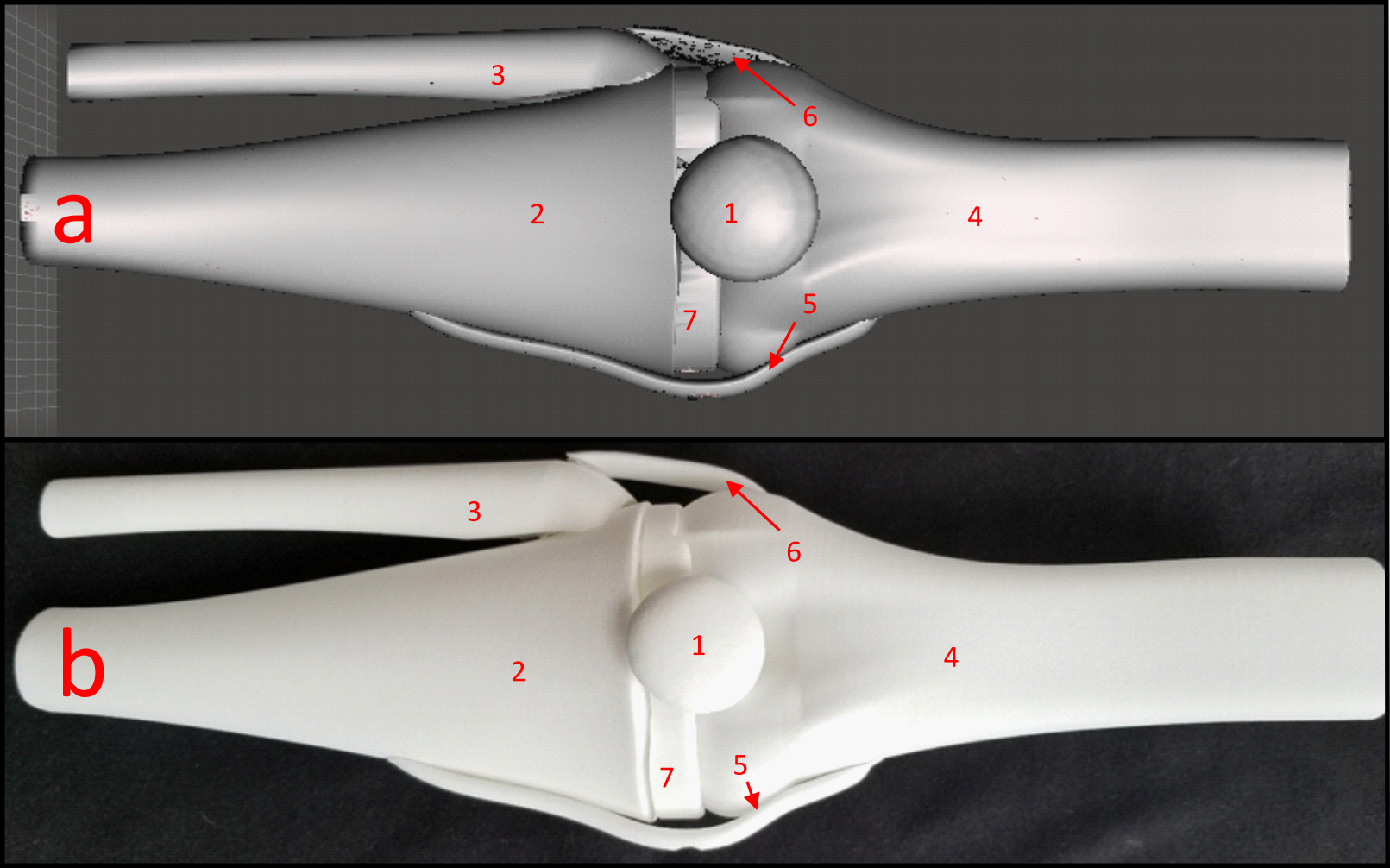
3D models of the human knee composed of the four major bones, four collateral ligaments, and bone cartilage were 3D printed and shown in Figure 1 with the anterior collateral ligament and posterior collateral ligament not visible.4 The organ molds were printed with White Natural Versatile Plastic (WNVP) with a wall thickness of 0.8 mm through the company Shapeways. The plastic used was nylon which possesses a relative permittivity value of 3.7 at 0.1 MHz and 2.75 for frequencies above 1 GHz, therefore the permittivity value of 2.75 is sufficient for simulations at 425.8 MHz.5,6 This study determines if the low relative permittivity of the nylon will affect the SAR profile at the thickness used and a greater thickness.7 Additionally, nylon’s melting temperature of 215 degrees Celsius will ensure that the structure will not degrade due to the heating effect of the RF coil during normal medical imaging procedures.8,9The hollow molds were designed using the Meshmixer hollow function with 1 hole added to each organ with a diameter ranging from 1.5-3 mm to ensure maximum surface uniformity of the phantom wall thickness. The relative permittivity, conductivity, and density values for the various tissues are shown in Table 1 with the tissue characteristics at 425 MHz and the Polyvinylpyrrolidone (PVP), NaCl, and water weights (g) to mimic those specific tissues.10-12
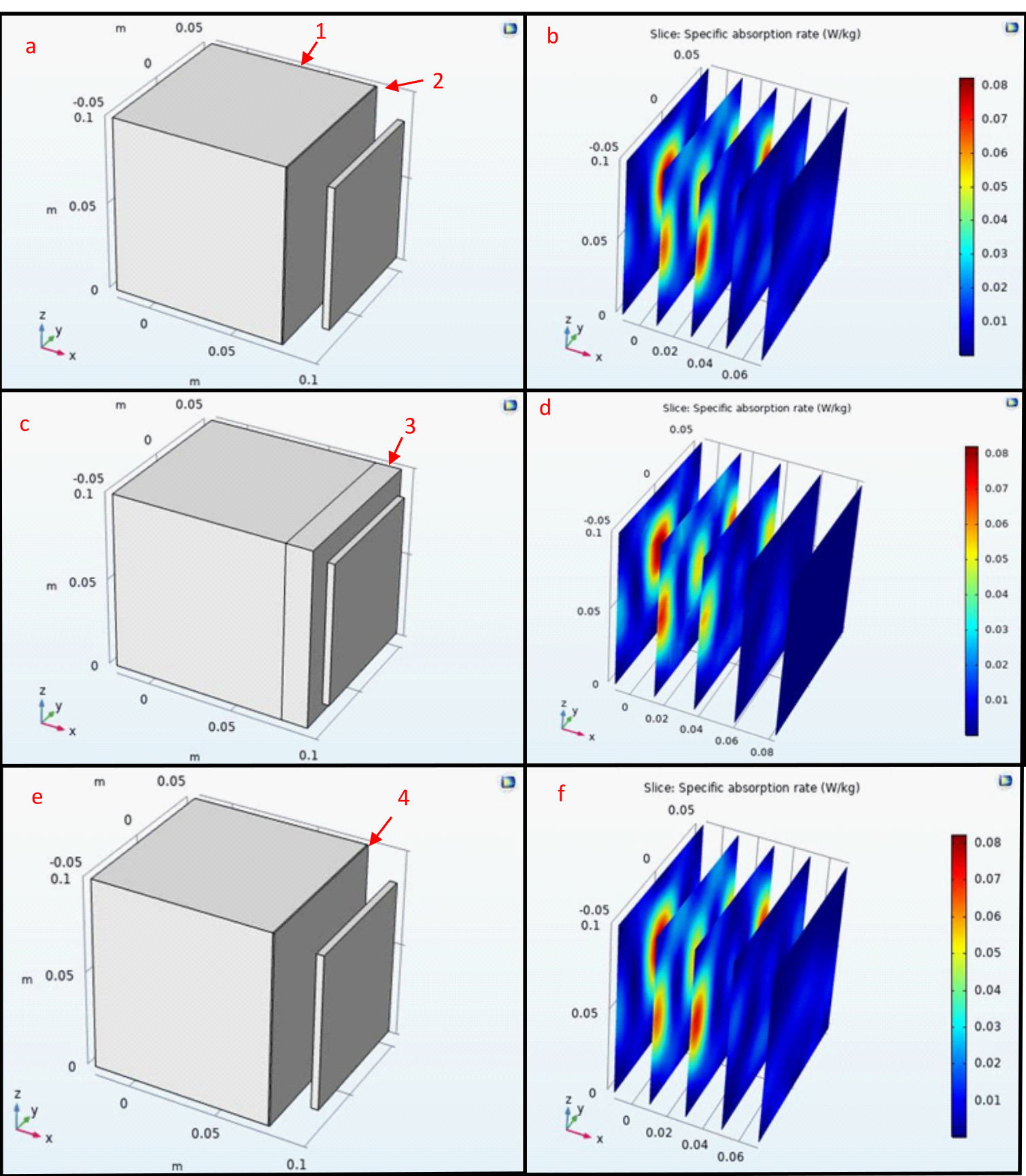
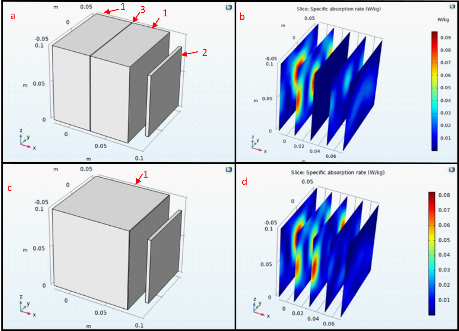
To determine if the wall thickness of the nylon will alter the RF field pattern an analysis with COMSOL utilizing the electrical conductivity and relative permittivity of nylon, and water at 425 MHz was conducted. To model if the nylon will affect the SAR, simulations were performed with a nylon layer of 8 cm and 0.8 mm between the water and the antenna. Next the effects of a 0.8 mm nylon barrier in between two domains of water were simulated and all of the nylon simulations were compared to a water only baseline.
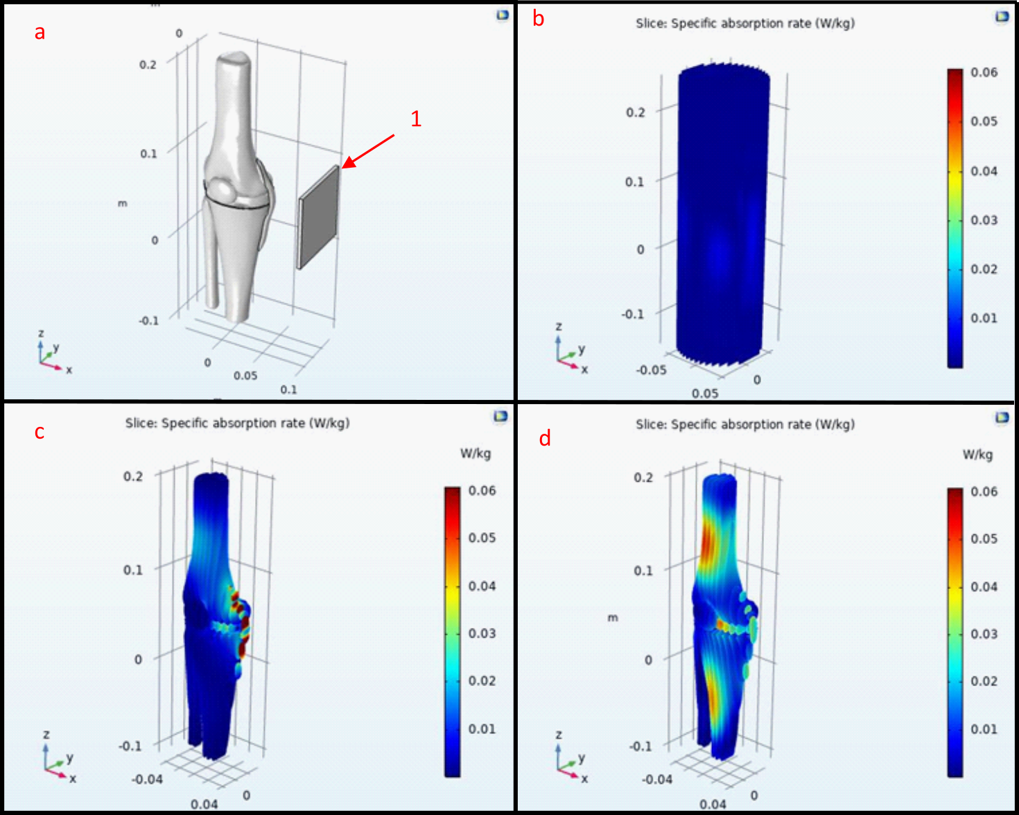
The same antenna was used to simulate three phantom models to analyze the field profile and amplitude without the inclusion of the nylon containers. The first was the 3D knee phantom exposed to air, second was the knee phantom encapsulated within a water cylinder phantom with a radius of 0.3 m, and the third test was only the water cylinder phantom. Each were then compared to determine which method would produce more definitive results utilizing the tissue properties in Table 1.
Results
The phantoms were filled with tap water for 24 hours to ensure that the phantoms would not show leakage or experience degradation. This time was selected under the assumption that the phantom would be filled and tested the day of filling so that the phantoms could be used to test different tissue characteristics. This shows that Nylon will not diffuse into the solution and alter the conductivity and permittivity of the phantom solution.The COMSOL simulations in Figure 2 show that the Nylon does not change the SAR by an observable amount even with a thickness of 8 cm, however in Figure 3 the layer of Nylon increased the SAR by 12.5%. This indicates the Nylon phantom will generate greater SAR when used within a water solution. Figure 4 shows the simulation results within the 3D phantom model in Figure 1 with the water only phantom generating a uniform SAR profile. When the phantom SAR is analyzed without the water phantom the simulation shows significant heat deposition on the medial collateral ligament (MCL) and lateral part of the femur. When the knee phantom is added to the water container the SAR on the MCL and femur is reduced and the SAR is increased in the cartilage and the anterior of the femur and tibia.
Discussion
Further work includes the creation and testing of these phantom models in a 10 Tesla MRI. Current results only consist of ideal simulation results and physical testing could show unwanted effects on the field distribution and intensity in ways we do not anticipate.13 Additional simulations and physical tests will be performed utilizing various coil locations and RF coils to determine which phantom model will generate results closest to human data. These studies will determine which of the proposed phantom models should be utilized for future MRI phantom research.Conclusion
This research demonstrates that 3D printed MRI phantoms can be generated with wall thickness of 0.8 mm and filled with solutions to mimic specific tissue types with minimal effect on the SAR within the phantom material. The simulations show that modeling of specific anatomical locations can determine susceptible regions.Acknowledgements
No acknowledgement found.References
1 Alon, L., Sodickson, D. K. & Deniz, C. M. Heat equation inversion framework for average SAR calculation from magnetic resonance thermal imaging. Bioelectromagnetics 37, 493-503, doi:10.1002/bem.21996 (2016).
2 Graedel, N. N. et al. An anatomically realistic temperature phantom for radiofrequency heating measurements. Magn Reson Med 73, 442-450, doi:10.1002/mrm.25123 (2015).
3 Haraikawa, M. et al. Simultaneous multi-slice MR imaging of the hip at 3 T to reduce acquisition times and maintain image quality. BMC Musculoskelet Disord 19, 440-440, doi:10.1186/s12891-018-2342-x (2018).
4 xristos. knee joint, <https://grabcad.com/library/knee-joint#> (2012).
5 Hu, X.-C. & Yang, H. H. in Comprehensive Composite Materials (eds Anthony Kelly & Carl Zweben) 327-344 (Pergamon, 2000).
6 Nassar, E., Lee, R. & Young, J. A probe antenna for in situ measurement of the complex dielectric constant of materials. Antennas and Propagation, IEEE Transactions on 47, 1085-1093, doi:10.1109/8.777136 (1999).
7 Bulumulla, S. B., Lee, S. K. & Yeo, D. T. B. Conductivity and permittivity imaging at 3.0 t. Concepts in Magnetic Resonance Part B: Magnetic Resonance Engineering 41B, 13-21, doi:https://doi.org/10.1002/cmr.b.21204 (2012).
8 Sastri, V. R. in Plastics in Medical Devices (ed Vinny R. Sastri) 121-173 (William Andrew Publishing, 2010).
9 Chakraborty, J. N. in Fundamentals and Practices in Colouration of Textiles (ed J. N. Chakraborty) 286-300 (Woodhead Publishing India, 2014).
10 Duan, Q. et al. Characterization of a dielectric phantom for high-field magnetic resonance imaging applications. Medical Physics 41, 102303, doi:https://doi.org/10.1118/1.4895823 (2014).
11 Gabriel, C. (1996). Compilation of the Dielectric Properties of Body Tissues at RF and Microwave Frequencies.
12 Foundation, I. I. Tissue Properties Database V4.0.
13 BOTTOMLEY, P. A. & ROEMER, P. B. Homogeneous Tissue Model Estimates of RF Power Deposition in Human NMR Studies. Annals of the New York Academy of Sciences 649, 144-159, doi:https://doi.org/10.1111/j.1749-6632.1992.tb49604.x (1992).
14 Mertz, E. L. et al. Makings of a brittle bone: Unexpected lessons from a low protein diet study of a mouse OI model. Matrix Biology 52-54, doi:10.1016/j.matbio.2016.03.005 (2016).
15 Yarrow, J. et al. Bone loss in a new rodent model combining spinal cord injury and cast immobilization. Journal of musculoskeletal & neuronal interactions 14, 255-266 (2014).
16 Scott, D. et al. Calf muscle density is independently associated with physical function in overweight and obese older adults. Journal of musculoskeletal & neuronal interactions 18, 9-17 (2018).
17 Foundation, I. I. Density.
Figures