3336
Studies of the static field homogeneity artefacts induced by the diamagnetism of HTS coils and solution to avoid them1Université Paris-Saclay, CEA, CNRS, Inserm, BioMaps, Orsay, France, 2Université Paris-Saclay, CNRS Center for Nanoscience and Nanotechnology, Palaiseau, France
Synopsis
High-Temperature Superconducting (HTS) radiofrequency coils can improve sensitivity by more than an order of magnitude, but their propensity to warp the magnetic field as a result superconducting diamagnetism could cause image degradation. We report on the observation of these B0 artefacts. They are shown to be predominant at lower working temperatures of the HTS coil (60 K) and negligible at 80 K and can be avoided altogether by cooling the HTS coil in B0. We also propose a phenomenological model of these field perturbations. This work studies and solves an important issue in the integration of HTS coil in MRI.
Introduction
High-Temperature Superconducting (HTS) radiofrequency (RF) coils can greatly improve the sensitivity of MRI, with Signal to Noise Ratios (SNRs) increased by more than an order of magnitude1. A possible complication of using this technology is the B0 inhomogeneity induced by dc magnetic flux expulsion, also known as superconducting diamagnetism. In the presence of a magnetic field, HTS materials generate screening currents on their surfaces/egdes, whose magnitude and distribution strongly depend on the temperature and magnetic history of the superconductor, notably whether it was cooled in the presence (field cooled) or the absence (zero-field cooled) of a magnetic field. So far, HTS coils have commonly been used at LN2 temperature, i.e. sufficiently close to the superconducting transition temperature Tc of the HTS material for such artefacts to have been (fortuitously) avoided. However, with better-controlled experimental parameters and new cryostats achieving lower temperatures, this becomes an issue. We report on the first observation of B0 artefacts generated by HTS coil diamagnetism2. We study these effects as a function of temperature and for different cooling conditions. We propose a phenomenological model reproducing the artefacts observed in the phase images, and we describe how they can be avoided.Material and Methods
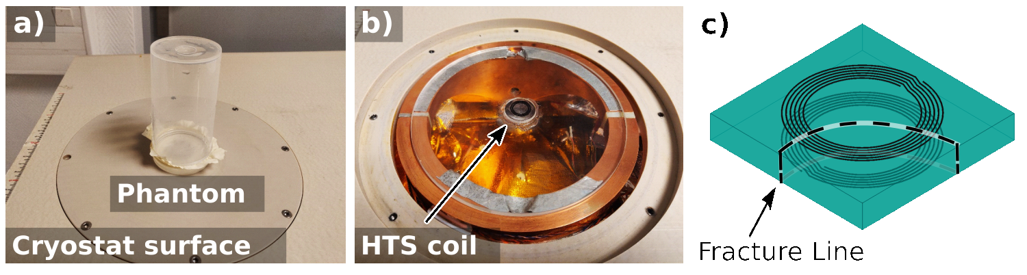
The equipment used for this experiment is shown in Figure 1. The cryostat3 is MRI compatible and can attain a minimal temperature of ~ 60 K (Figure 1b). The MRI system is a clinical 1.5 T set-up (Philips, The Netherlands). A whole-body RF coil was used for transmission/reception, and the MRI sequence was a standard 3D gradient-echo. The phantom is a cylinder of diameter 50 mm centered on the position of the HTS coil, on top of the cryostat (Figure 1a.b). The coil design is a 14.4 mm multi-turn Transmission Line Resonator4 (MTLR): a pair of six-turn YBa2Cu3O7-δ spirals (Tc = 86 K) on both sides of a Al2O3 substrate. For this experiment, we used a non-resonant antenna (Figure 1c) so as to avoid B1 artefacts while keeping intact the diamagnetic response of the HTS material. 3D MR images were acquired after zero-field cooling (outside the MRI scanner), field cooling (inside the MRI scanner) and for different temperatures varying from 60 K to 90 K.Results
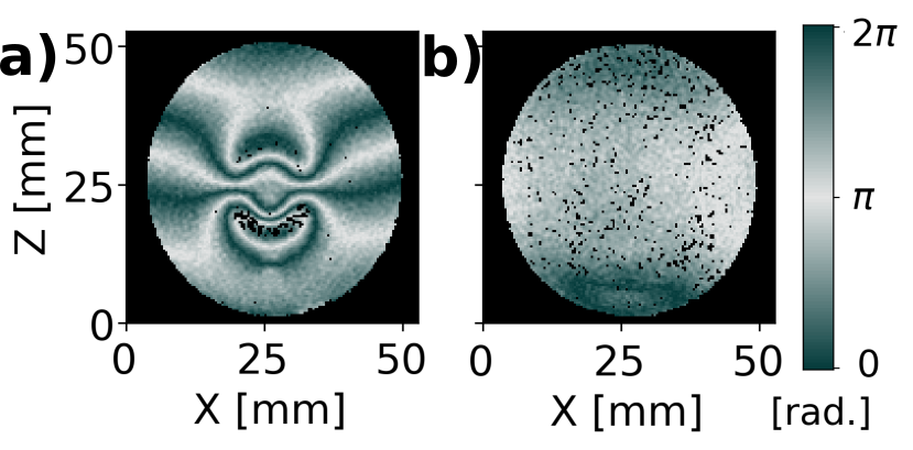
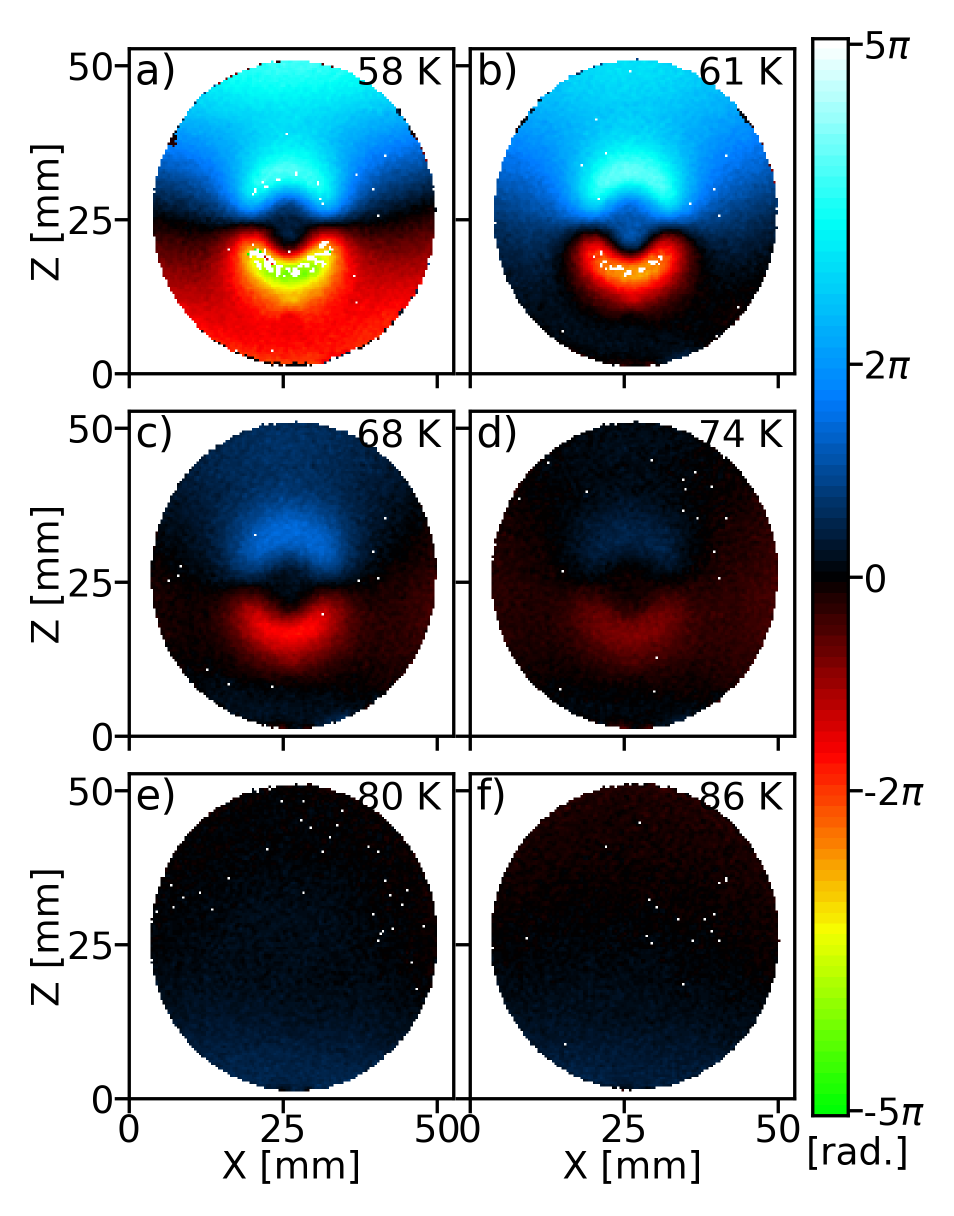
In Figure 2, we present two phase images in a coronal plane located 4.2 mm away from the HTS coil. The image in Figure 2a was acquired after zero-field cooling. We observe signal loss and important perturbations in the phase image. These anisotropic artefacts are minimal toward y ( $$$\perp\vec{B}_0$$$) and maximal toward z ($$$\parallel\vec{B}_0$$$). The image in Figure 2c was acquired after field cooling. The image is free of artefacts. In Figure 3, we present the results of the temperature study after zero-field cooling. The phase data were unwrapped5. The B0 artefacts show a strong dependence on temperature; the shape and size of the phase pattern do not change, but the amplitude is continuously reduced as the temperature increases, up to the point where it becomes almost unnoticeable at 74 K (Figure 3e) and nonexistent at T > 80 K (Figure 3f).Model
The B0 artefacts observed in the phase images can be reproduced with a simple phenomenological model of the diamagnetism of the HTS coil. This model uses the coil geometry and computes the magnetic field $$$\vec{\Delta B}=I_0\vec{\Delta b}$$$ generated by an in-plane screening current I0 circulating around the coil perimeter. The phase $$$\phi$$$ at position $$$\vec{r}$$$ is expressed as :$$$\phi(\vec r,T)=\gamma T_EI_0\Delta b_z(\vec{r},\vec{r}_0)+\phi_0(T)+\vec{\phi}_r\cdot\vec{r},\quad(1)$$$
where $$$\Delta b_z$$$ is the z-component of $$$\Delta\vec{b}$$$, $$$\vec{r}_0$$$ is the position of the antenna relative to the sample, $$$\gamma$$$ is the gyromagnetic ratio of the proton, $$$T_E$$$ is the echo time, and $$$\phi_0$$$, $$$\vec\phi_r=[\phi_x,\phi_y,\phi_z]$$$ and $$$I_0$$$ are fitting parameters determined by linear regression for each temperature.
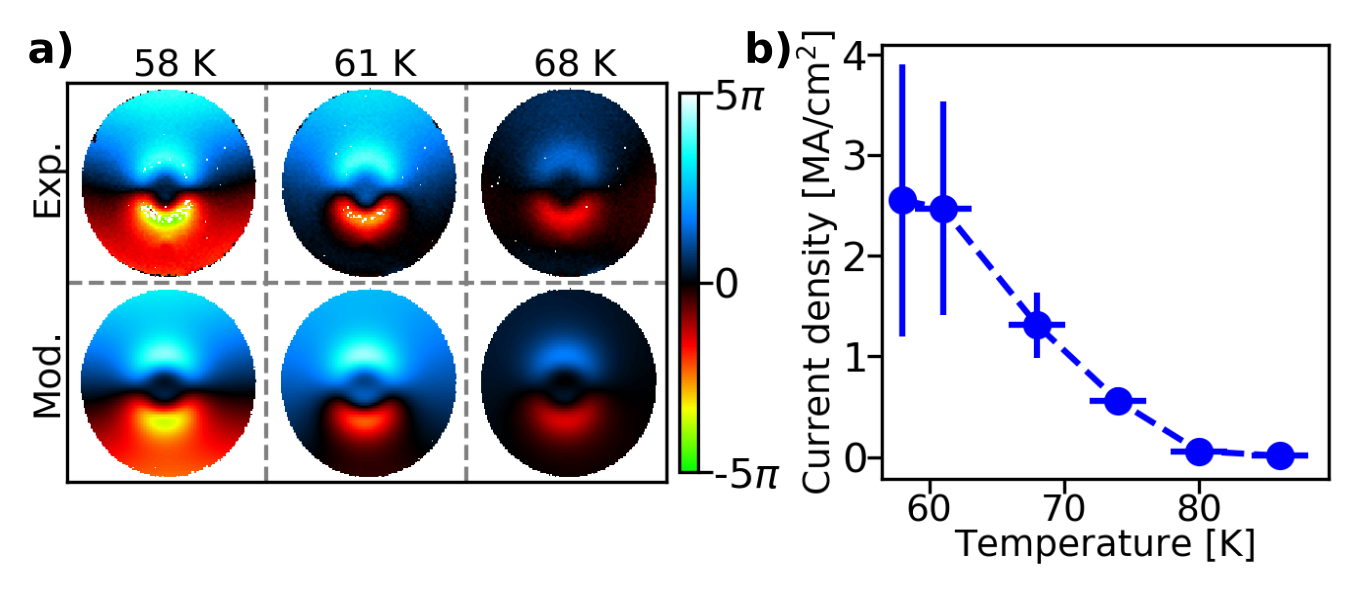
Experimental and modelled phase images displayed in Figure 4a are in good agreement. At 80 K, the field inhomogeneities attain 0.16 ppm in the phantom, whereas they attain 6.6 ppm at 58 K. This generates a field gradient of ~ 8 mT/m (at 58 K), inducing a phase drift of ~1.4 $$$\pi$$$ over a single voxel, ultimately leading to signal loss. From the current $$$I_0(T)$$$, we estimate the screening current density $$$j$$$ in the YBa2Cu3O7-δ strip (Figure 4b). We find that $$$j$$$ ~ 2.6 MA/cm2 at 58 K decreasing to $$$j$$$ ~ 0.4 MA/cm2 at 77 K. This tracks the temperature dependence of the HTS coil critical current density6 $$$j_c$$$.
Conclusions
B0 artefact arising from superconducting diamagnetism in HTS coil can severely degrade image quality in MRI. However, this can be avoided by either working at temperatures close to Tc, or by field cooling the HTS coil inside the MRI scanner. This work studies and solves an important issue in the implementation of HTS coil and provides better understanding of the experimental conditions required to obtain better images with this technology.Acknowledgements
Experiments were performed on the 1.5 T MRI platform of CEA/SHFJ, affiliated to the France Life Imaging network and partially funded by the network (grant ANR-11-INBS-0006).References
1. Poirier‐Quinot, M. et al., Magn. Reson. Med., (2008).
2. Labbé, A. et al. Appl. Phys. Lett., (in press).
3. Saniour, I. et al., Rev. Sci. Instrum., (2020).
4. Serfaty, S. et al., Magn. Reson. Med., (1997).
5. Abdul-Rahman, H. S. et al., Appl. Opt., (2007).
6. Sierra J. D. et al., ACS Appl. Nano Mater., (2020).
Figures