3335
Eight channel B0 shim array as add-on for ultra-high field systems1Philips Healthcare, Copenhagen, Denmark, 2Danish Research Centre for Magnetic Resonance, Centre for Functional and Diagnostic Imaging and Research, Copenhagen University Hospital, Hvidovre, Denmark, 3Section for Magnetic Resonance, DTU Health Tech, Technical University of Denmark, Kgs Lyngby, Denmark, 4Athinoula A Martinos Center for Biomedical Imaging, Department of Radiology, Massachusetts General Hospital, Charlestown, MA, United States
Synopsis
We have simulated and manufactured a shim coil array specifically designed to address fronto-temporal B0 inhomogeneities at 7T. The shim array is driven by an open-source amplifier, and facilitates slice-wise dynamic shimming. Complexity and costs are purposely kept low to allow manufacturing without prior expertise in electronics design and without access to extensive electronics manufacturing facilities.
Introduction
Patient-induced B0 inhomogeneities is a significant source of image and spectroscopic data degradation at 7T. To counter this, scanners are typically equipped with additional shim coils, designed to generate spherical harmonic-varying fields across the entire imaging volume. However, for whole-brain MR, adequate shimming of the fronto-temporal region for low-bandwidth sequences (e.g EPI readout used for fMRI and DWI), T2* weighted sequences and spectroscopy remain a challenge.Shim coils designed to locally improve B0 homogeneity are attractive as a supplement, as they facilitate specifically addressing areas such as described above. Dynamic updating of the generated shim field is in addition feasible without inducing noteworthy eddy currents. Several local-shim approaches have been shown for improved brain shimming, including a six channel, variable positioning setup [1], a 48-channel combined RF and shim coil [2], and a 32-channel combined RF and shim coil [3] with additional face loops [4]. These setups showed great shimming capabilities but relied on dedicated and complex RF coil setups.
Here we present a shim coil array specifically designed to improve shimming in the fronto-temporal brain region. The array is designed to be mounted on top of a typical 7T head coil (Nova Medical, Wilmington, MA, U.S). The design is freely accessible and can be manufacturing with limited electronics experience and equipment.
Methods
A shim coil array was simulated by varying position, number of coils, coil radius, inter-coil distance, rotation in a coronal plane, offset in the feet-head direction, and limited to a single curved surface to fit the outer diameter of the RF coil’s transmit component (Tx-coil). Based on the simulations a coil layout as shown in figure 1 was chosen (8 coils, inner coil diameters: 70mm, 50 windings, 90mm from the center of the central coil to the center of 7 peripheral coils). Winded coils were attached to a flexible acrylic sheet using zip ties. The sheet was bend into the shape of the outer surface of the Tx-coil, and the coil was embedded in epoxy to minimize vibration when operated. The shim array was positioned relative to the head coil by plastic screws going through the acrylic plate and into 3D printed brackets screwed onto the Tx-coil. The shim array before being embedded in epoxy (top) and mounted on the head coil (bottom) is depicted in figure 2. A printable coil-placement guide, 3D-printable brackets and a 3D-printable coil-winder is accessible at https://resources.drcmr.dk/BrainShimArray/.To drive the shim-array, we used an open-source, 8-channel, class-A amplifier [5]. Control of the amplifier was done by fiber optic cabling, facilitated by a Teensy 3.5 (PJRC, Sherwood, OR, U.S.). Current-carrying cables from the amplifier to the shim coils were pair-wise twisted and passed through the cable-management system of the scanner. The amplifier was supplied 12V, facilitating up to ±2.5A on each shim array element. B0 shim fields were acquired using a large balloon containing salt water as phantom.
A B0 map of a healthy volunteer was acquired using the scanner’s (Philips 7T Achieva, Best, Netherlands) 1st and 2nd order shimming. A current-constrained shimming algorithm generated settings for 2 scenarios: (1) Static shim by the scanner, and static shim by the shim array (“static shimming”). (2) Static shim by the scanner, but dynamic slice-wise shimming by the shim array and updating of the scanner's reference frequency, f0 (“dynamic shimming”). Simulated settings were transferred to the Teensy, which updated shims when triggered by scanner-provided TTL-pulses. Performance of the shimming was evaluated by the standard deviation (std) across a brain-masked B0 map.
Results
Figure 3 depicts measured B0 maps when using only the scanner’s 1st and 2nd order shims (top), static shimming (mid) and dynamic shimming (bottom). A high degree of similarity between simulated and measured B0 fields was generally observed (<1Hz difference in std), verifying the applicability of the shimming algorithm. Static shimming improved the std from 39Hz to 31Hz, which is similar performance to [3] (verified by simulations). Dynamic shimming further improved the B0 homogeneity, resulting in a std of 25Hz.Discussion
We optimized a multi-coil shim array specically for improving whole-brain shimming at 7T, making a compromise between construction complexity and shimming performance. Placing 8 multi-turn shim coils outside the RF shield of the Tx-coil allows for low interaction with the RF coil, but still provides significant improvements over static 1st and 2nd order shimming. Simulations suggest slightly improved performance if the shim array is placed between the RF transmit and receive coil, however this would require a more complex design to address coupling to the transmit and receive coil. While other hardware designs have shown better performance than here presented, these feature a vastly more complex design. Simulations predict further improvement is obtainable from using the presented shim array in conjunction both f0 updating and 1st order shimming, but requires extensive pulse programming to verify in measurements.Conclusion
We have presented an easily reproduced, effective local shim array design, specifically designed to address fronto-temporal B0 inhomogeneites at 7T. In a healthy volunteer the shim array improved whole-brain standard deviation from 35Hz to 31Hz using static shim settings, and to 25Hz using dynamic slice-wise shimming.Acknowledgements
The 7T scanner was donated by the John and Birthe Meyer Foundation and The Danish Agency for Science, Technology and Innovation (grant no. 0601-01370B).References
[1] Juchem, Christoph, et al. "Magnetic field homogenization of the human prefrontal cortex with a set of localized electrical coils." Magnetic Resonance in Medicine: An Official Journal of the International Society for Magnetic Resonance in Medicine 63.1 (2010): 171-180.
[2] Juchem, Christoph, et al. "Dynamic multi-coil shimming of the human brain at 7 T." Journal of magnetic resonance 212.2 (2011): 280-288.
[3] Stockmann, Jason P., and Lawrence L. Wald. "In vivo B0 field shimming methods for MRI at 7 T." NeuroImage 168 (2018): 71-87.
[4] Stockmann, Jason P. et al. Improving the efficiency of integrated RF-shim arrays using hybrid coil designs and channel placement and compression via a genetic algorithm, Proc. Intl Soc Magn Reson Med, 2016, p. 1153
[5] Arango N, Stockmann JP, Witzel T, Wald L, White J, “Open-source, low-cost, flexible, current feedback-controlled driver circuit for local B0 shim coils and other applications”, Proc. Intl Soc Magn Reson Med, 2016, p. 1157
Figures
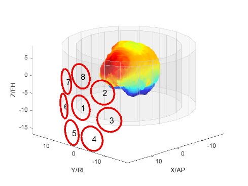
Figure 1:
Simulated,
optimal shim array positioning relative a human brain and an RF head coil. The
inner ring represents the RF coil’s receive component, while the outer ring
represents the transmit component of the coil (Tx-coil). The shim array follows
the out curvature of the Tx-coil.
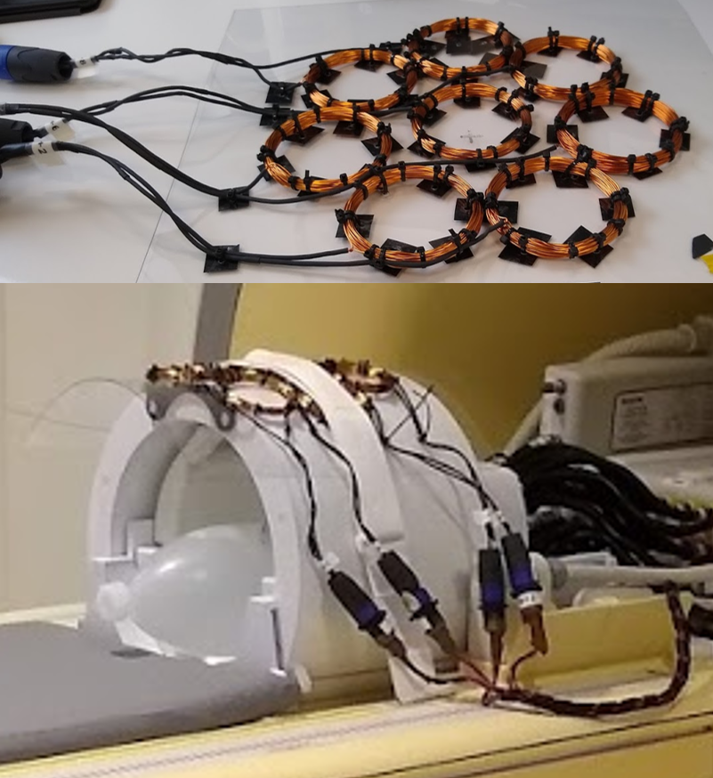
Figure 2:
Top: The manufactured shim array right before it was embedded in epoxy.
Bottom: The shim array mounted on top of the RF transmit coil.
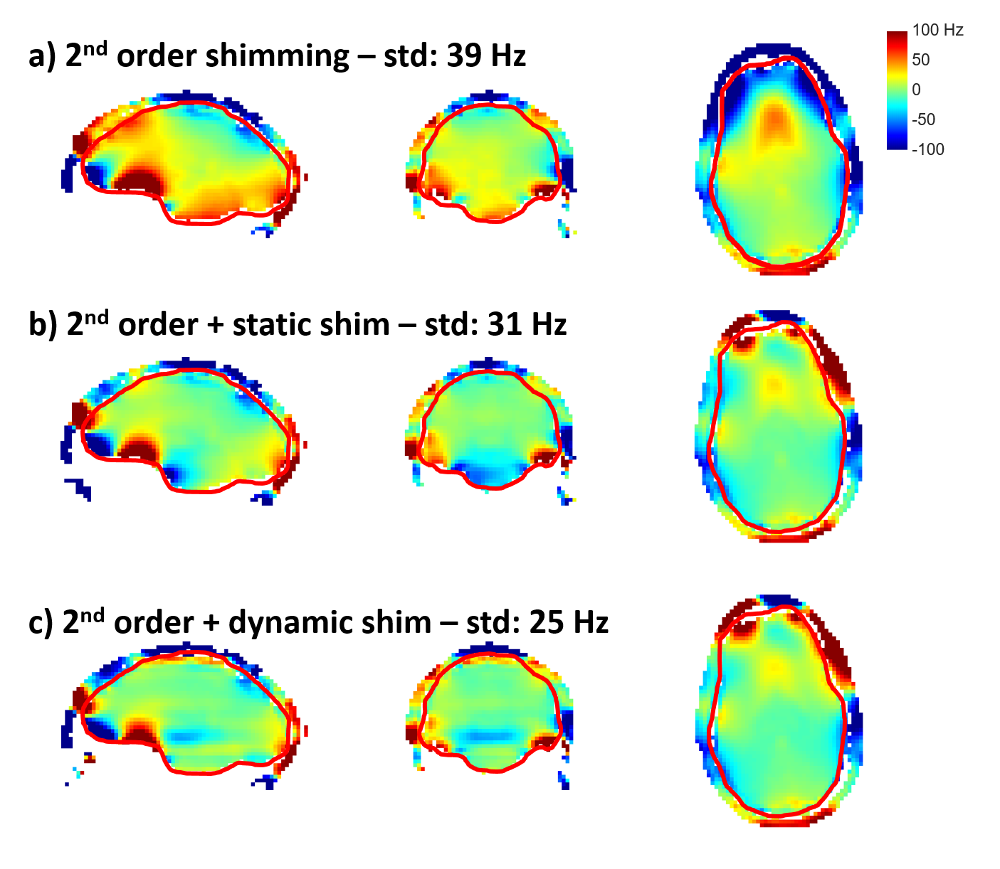
Figure 3:
B0 maps showing residual B0 inhomogeneities after employing the scanner-featured 2nd order shimming (top), additionally static (mid) and dynamic (bottom) shimming by the presented shim array. For all cases, simulations showed high similarity to measured B0 fields (<0.3Hz difference in std).