3332
Correct K-space coordinates and gradient coupled $$$B_0$$$ variation for Spiral imaging using the current monitor1Department of Radiology, Mayo Clinic, Rochester, MN, United States, 2Philips Research, Hamburg, Germany, 3Philips Healthcare, Gainesville, FL, United States
Synopsis
Error from inaccurate eddy current assessment has been a critical issue in spiral imaging. A model is established to estimate both the gradient field and its induced B0 variation from the measured current of the gradient amplifier. The correction improves the geometric consistency between both spiral-in and spiral-out images. The results suggest that the present work have potential to improve quality of spiral imaging.
Introduction
MR imaging with spiral trajectories is known for its scan efficiency but is prone to artifacts which limit application in clinical practice. One of the common artifacts is due to gradient imperfections and spurious magnetic field caused by eddy currents during spatial encoding leading to both inaccurate k-space mapping and erroneous phase accumulation due to gradient coupled $$$B_0$$$ variation. Recently, correction methods making use of the linear gradient system model derived from the measured gradient field have been extensively applied1,2 to improve approximation of the k-space trajectory for a given gradient system. Among these methods, the model relating the current from the gradient amplifier with the gradient response, the current gradient modulation transfer function (CGMTF), has been found more robust with fewer nonlinear effects3,4. As gradient coupled $$$B_0$$$ variation has influence on the geometry of the image, the present work developed a model to account for the $$$B_0$$$ coupling effect based on the CGMTF approach in order to improve the geometric fidelity of spiral imaging.Modelling Gradient Response
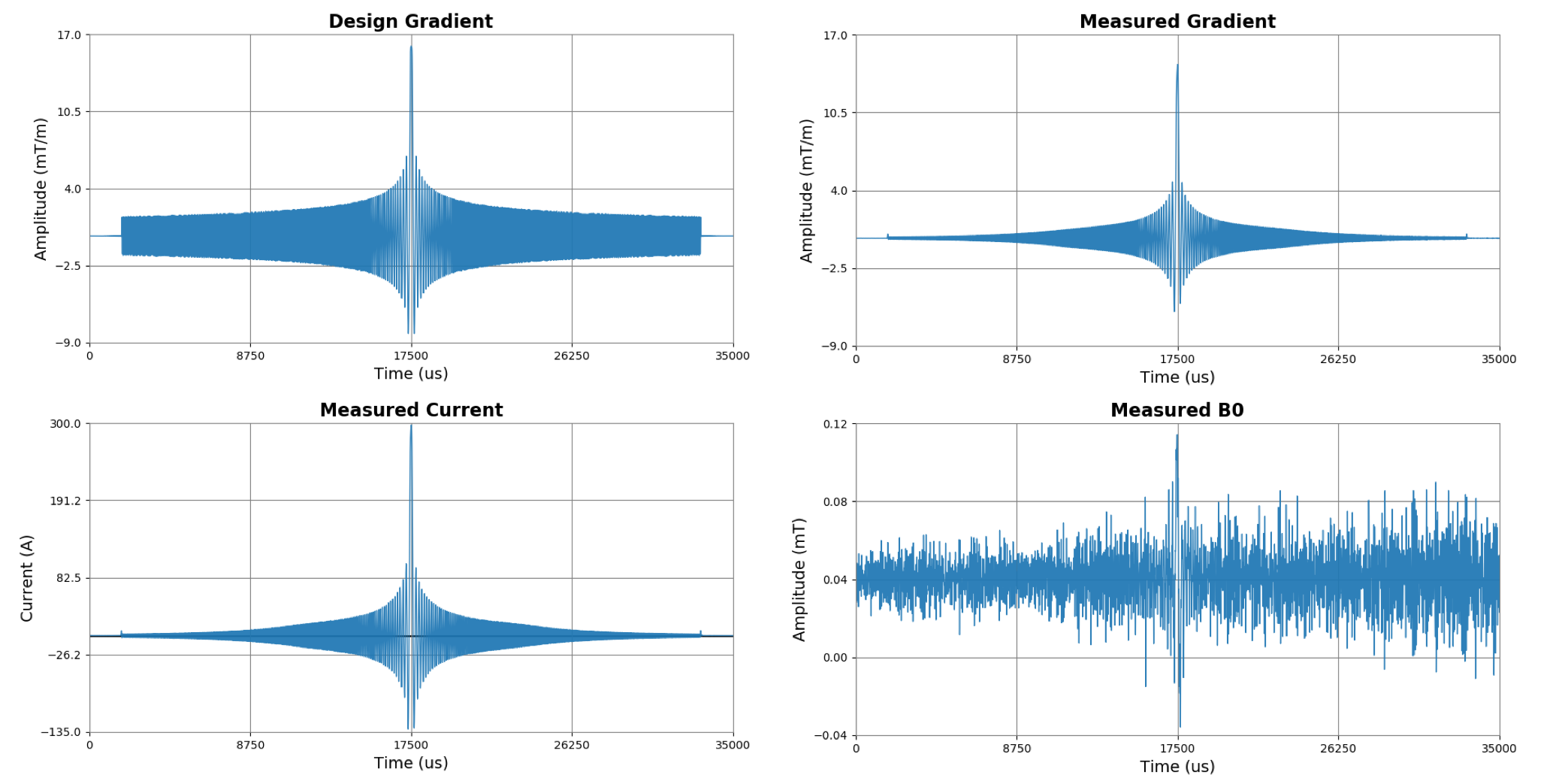
A dynamic field camera (DFC, SKOPE, Zurich, Switzerland) was used to measure the temporal changes of the magnetic field distribution inside the magnet during gradient activity. A series of slew limited chirp waveforms sweeping from -16kHz to +16kHz with variable maximal amplitudes were served as the probing inputs to induce the corresponding currents from the gradient amplifier and the changes of magnetic field in the scanner. The current measurement was performed via an embedded current sensor at the output of the gradient amplifier. Fig 1. shows one of the input waveforms having maximal amplitude at 16mT/m along with the corresponding measured current, the measured $$$B_0$$$ and the gradient field. As the current measured include the shim current and a constant $$$B_0$$$ offset, a model considering both the 0th and the 1st order response is utilized in the present CGMTF implementation to take these coupled shimming conditions into account. The CGMTF model in this work is described as $$ \begin{bmatrix} G_x(f) \\ G_y(f)\\G_z(f)\\B_0(f) \end{bmatrix} = \begin{bmatrix} M_{xx}(f) & M_{xy}(f) & M_{xz}(f) \\ M_{yx}(f) & M_{yy}(f) & M_{yz}(f) \\M_{zx}(f) & M_{zy}(f) & M_{zz}(f)\\M_{B_0x}(f) & M_{B_0y}(f) & M_{B_0z}(f) \end{bmatrix} \begin{bmatrix} I_x(f) \\ I_y(f)\\I_z(f) \end{bmatrix}+\begin{bmatrix} G_{x,offset} \\ G_{y,offset}\\G_{z,offset}\\B_{0,offset} \end{bmatrix} $$$$$ I_{x,y,z}$$$ are the current readings along the three different axes. $$$G_{x,y,z}$$$ are the corresponding gradient fields, and the main field measured by DFC. M is the MTF matrix converting the currents to the magnetic fields. $$$B_{0,offset}$$$ primarily accounts for changes of main field shifting and is consequently ignored when applying the model for correction. The other three gradient offsets, $$$ G_{(x,y,z),offset}$$$ represent the gradient environment after shimming.
Experiment Setup
Phantom experiments were conducted on a 1.5T scanner (Ambition, Philips Healthcare, Best, Netherland). A 2D gradient echo sequence adopting spiral in-out trajectory is used for imaging with TR = 500ms, TE = 15ms, acquisition window = 20ms, and in-plane resolution $$$1 \times 1 mm^2$$$. The spiral-in and the spiral-out data were reconstructed separately. The k-space trajectory used for reconstruction were calculated by (1) the predefined scanner’s model, (2) the measured fields by the DFC, and (3) the prediction by the linear CGMTF model.Results
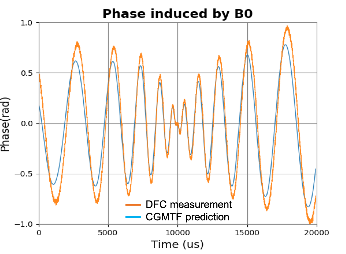
Fig 2. shows the phase accumulation of $$$B_0$$$ variation induced by the one of the spiral gradient during data acquisition. These time-varying phases has effects on the acquired data leading to geometry alteration. If this effect is not properly addressed, spatial mismatch can be anticipated by comparing the images from the spiral-in and the spiral-out trajectories.Fig 3. shows the comparisons of the spiral-in and spiral-out images reconstructed using the tested procedures with different field estimation methods. Geometric discrepancies between the spiral-in and spiral-out images can be found in the reconstruction based on the scanner’s predefined eddy current compensation model including edge blurring, rotation and translation. The blurring along the edges and the rotation were found reduced as more accurate k-space coordinates measured by the DFC and modelled by the CGMTF are applied. However, translation and distortion still exist in the cases that only gradient fields are corrected. The correction for B0 coupling further amends the translation and the distortion improving geometric consistency between the images of the two sampling trajectories.
Discussions
Although most scanners use a predefined eddy current correction model for image correction, the results showed that site-specific calibration can improve results. Inaccuracy in the estimation of the eddy current effect degrades the geometric fidelity of the image. Such error could be mitigated with a model providing better estimation in the gradient information and $$$B_0$$$ changes. While the CGMTF model could provide better understanding of the magnetic field to improve image quality, the artifact arising from the susceptibility between two objects is beyond its scope and requires further investigation.Conclusion
The present work established a model correlating the current measurement from the gradient amplifier with the gradient field and the induced $$$B_0$$$ variation. The model is suggested to provide k-space coordinates and the $$$B_0$$$ coupling with better accuracy to improve geometry fidelity for spiral imaging.Acknowledgements
This work is supported in part by Philips Healthcare.References
1. Rahmer, J., et al., Rapid acquisition of the 3D MRI gradient impulse response function using a simple phantom measurement. Magn Reson Med, 2019. 82(6): p. 2146-2159.
2. Vannesjo, S.J., et al., Gradient system characterization by impulse response measurements with a dynamic field camera. Magn Reson Med, 2013. 69(2): p. 583-93.
3. Rahmer, J., et al. Trajectory calculation for spiral imaging based on concurrent reading of the gradient amplifiers’ internal current sensors. in 2020 ISMRM & SMRT VIRTUAL CONFERENCE and Exhibition. 2020.
4. Nussbaum, J., et al. Nonlinearity and thermal effects in gradient chains: a cascade analysis based on current and field sensing. in ISMRM 27th Annual Meeting and Exhibition. 2019. Montreal.
Figures